Optical Fiber Splice Loss
You can get Fiber Optic Fusion Splicer, Fusion Splicing Machines, and Fusion Splice Protection Shrink Sleeves from Fiber Optics For Sale Co.
Optical power loss at the splicing point of two ends of optical fiber is known as splice loss. In this tutorial splice loss measurement technique, extrinsic & intrinsic factors effecting splice loss and typical settings of splicing instrument are described.
>> Fusion Splicing Splice Loss
Fusion splicing is a technique to join two fibers ends. Optical power loss at the splicing point is known as splice loss.
>> How splice loss can be measured?
An Optical Time Domain Reflectometer (OTDR) can be used for splice loss measurement. A cable section-containing splices are normally shown as knees on the optical power loss OTDR graph. As per the procedure (ANSI/TIA/EIA-455-8-2000), splice loss measurements with an OTDR must be conducted from both directions and averaged (by adding with signs)for accurate splice loss. Below is the graphical picture of ‘gainers’ and ‘exaggerated losses’ measurements; the effect on actual splice loss is relatively low.
* Where DB(±R) represents “true” or “actual” loss, L(±R) represents loss as seen by the OTDR, B(±R) represents loss (backscatter) due to MFD (mode field diameter) mismatch as seen by the OTDR, and ω1 and ω2 represent the respective fiber mode-field diameters
While these differences in MFD result in “gainers” and exaggerated losses” in uni-directional OTDR.
It is important to remember that actual splice-loss is the measured splice-loss in both directions divided with two.
Example:
>> On which parameters splice loss is dependent?
The parameters, which control loss in any fiber joining method, can be classified as Intrinsic and Extrinsic parameters.
>> Intrinsic Parameters
Intrinsic or fiber related parameters are determined when the fiber is manufactured and cannot be controlled by the individual doing splicing.
Mode Field Diameter (MFD) is the most important intrinsic parameter. More splice loss can be observed for higher difference in MFD values. The MFD is a characteristic, which describes the mode field (cross-sectional area of light) traveling down a fiber at a given wavelength. When fibers with different MFD values are spliced together, a MFD mismatch occurs at splice point. With the help of the following formula splice loss due to MFD mismatch can be calculated from MFDs (in um) of two fibers
For example, if the MFD of two fibers are 8.8um and 9.6um, splice loss between these two MFD values is 0.035 dB as per the above equation.
Figure 1 shows calculated splice loss as per equation 3 with various MFD combinations of range 8.8-9.8 Em. Higher differences in MFD values between two fibers increases splice loss.
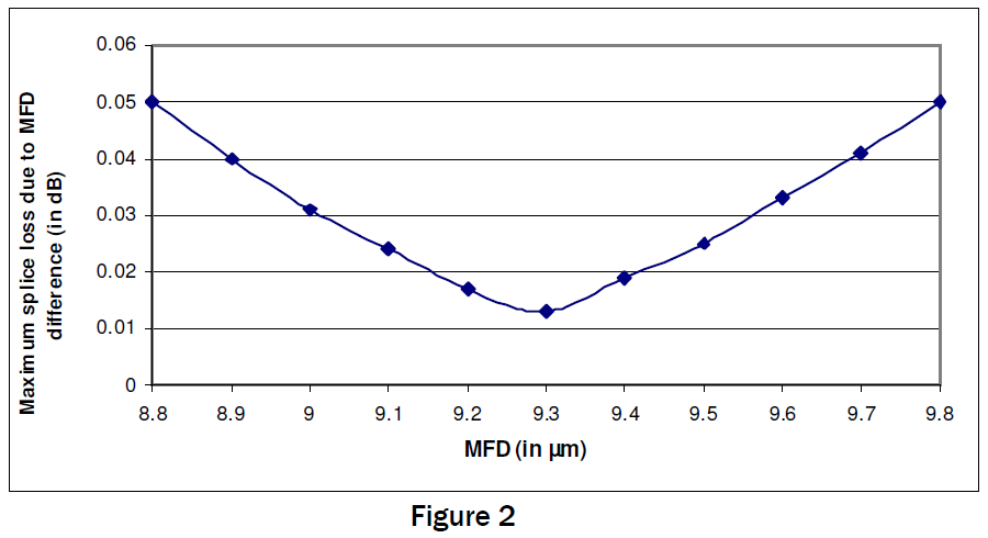
Figure 2 shows maximum splice loss of fiber with particular MFD value with any other fiber of MFD range 8.8-9.6 um. Splice loss of fiber with MFD 9.3 um is lowest when spliced with any other fiber of range 8.8-9.6 um. Splice loss increase in either side of the band and reaches 0.05 dB at two extreme points. Thus it is better to maintain MFD value close to 9.3um to achieve least splice loss with any other fibers.
>> Extrinsic Parameters
Extrinsic, or splice process related parameters are those induced by splicing methods and procedures. Splice process parameters include lateral and angular alignment, contamination at the fiber end and core deformation due to un-optimized heating & pressing. These external parameters can be controlled/minimized by improving skill of the individual doing splicing and by automated fiber alignment and fusion cycles.
It has been observed that splice loss between two identical fibers with same MFD and geometry parameters is as high as 0.04 dB. This excess loss is due to miss alignment and other splicing process parameters. Figure 3 shows fiber end conditions with various un-optimized splicing parameters.
Other important extrinsic parameter is fiber end angle. Proper fiber end preparation is the most fundamental step to get acceptable splice loss. Generally end angle less than two degrees gives acceptable field splice loss. End angle is dependent on condition of cleaver and cleaver blade. Typical end angle of well – maintained cleaver is around one-half degree. Figure 4 is showing comparison between bad and good cleaving. It has been observed that extrinsic parameters can give splice loss as high as 0.4 dB. By controlling extrinsic parameters, acceptable field splice loss can be achieved.
>> Recommended Splicing parameters for G652 fibers
Parameters
- ARC duration 01.50sec
- Pre-fusion 00.10sec
- ARC gap 10.00μm
- Overlap 15.00μm
- ARC power 00.20step
Alignment method
- Auto Core Alignment
Fiber end check
- Auto cleave angle check
Measurement method
- Optical time domain reflectormeter (OTDR)


