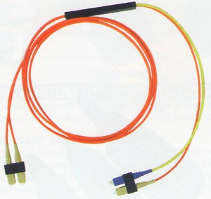
Mode Conditioning Cable (Mode Conditioning Patch Cord) – How to Use It?
Get Mode Conditioning Cable from here
Or click on the following piture
Why Do We Need Mode Conditioning Cable?
The simple answer to this question is: To allow Gigabit 1000 Base-LX single mode equipment, such as routers and switches, to be used on existing 62.5um or 50um multimode cable plants.
The Background History
Because of bandwidth limitations of multimode fiber, future multi-gigabit fiber optic LAN networks will be based on single mode fiber cables. Actually most new fiber installations include at least some single mode fiber in the cable plant.
Most current LAN networks are composed of about 90% multimode fiber. As the fiber cable plant is upgraded to single mode fiber cables, we must also provide a migration path that continues to reuse the installed multimode cable plant for as long as possible.
However, there are some technical issues involved when using single mode equipment on existing multimode cable plant. The biggest problem is caused by Differential Mode Delay (DMD).
The Technical Side of the Story
Multimode fibers are designed for LED light sources. When LED light is coupled into multimode fiber, it is typically an overfilled launch condition, which results in equal optical power being launched into all fiber modes.
However, single mode lightwave equipment such as Gigabit 1000Base-LX equipment uses single mode laser source. Since single mode laser source is highly collimated, when it is coupled to multimode fibers, it tends to produce an underfilled launch condition, which results in optical power not equally distributed into all fiber modes.
As a result, engineers have discovered that bandwidth measured using overfilled launch condition (LED) is not always a good indication of link performance for laser applications over multimode fiber. This is explained in the below figure.
When a fast rise-time laser pulse is applied to multimode fiber, significant pulse broadening occurs due to the difference in propagation times of different modes within the fiber. This pulse broadening is known as differential mode delay (DMD) and can be large enough to render a gigabit link in operable.
To allow for laser transmitters to operate at gigabit rates over multimode fiber without being limited by DMD, a special type of fiber optic patch cable was designed to “condition” the laser launch and obtain an effective bandwidth closer to that measured by the overfilled launch method.
And this special type of fiber patch cable is called “Mode Conditioning Cable” or “Mode Conditioning Patch Cord”.
The point is to excite a large number of modes in the fiber, weighted in the mode groups that are highly excited by overfill launch conditions, and to avoid exciting widely separated mode groups with similar power levels.
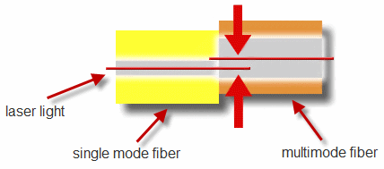
This is achieved by launching the laser light into a single mode fiber, then coupling it into a multimode fiber that is off-center relative to the single mode fiber core. This is shown below.
Different offsets are required for 50um and 62.5um multimode fibers. Engineers have found that an offset of 17~23um can achieve an effective modal bandwidth equivalent to the overfill launch method for 62.5um multimode fibers. And an offset of 10~16um is good for 50um multimode fibers.
Notes When Using Mode Conditioning Cables (Mode Conditioning Patch Cord)
When you are connecting your Gigabit 1000Base-LX equipment (single mode) to your multimode cable plant, make sure that you connect the yellow leg of the mode conditioning cable (single mode side) to the transmitter side of your equipment, and the orange leg (multimode) side of the cable to the receiver side of the equipment. It is imperative that this configuration be maintained on both ends.


