The Near-Field Scanning Technique
The advantage of scanning the near-field intensity distribution of the test fiber directly is that there is no need for mathematical transformations of the measured data. If the intensity distribution of the aperture field, Ea(r)2,is measured then it can be input directly into equation 2-2 to give the effective area. The main difficulty with measuring the near-field is that it extends over very small area – typically 5-10-mm in diameter. Consequently, optics are required to produce a magnified image of the field that can be scanned radially using a detector with a pinhole in front or a fibre pigtail. The optical system must be carefully constructed to ensure that the magnified image is a faithful representation of the end of the test fibre. A high numerical aperture system is required to avoid smearing the image by truncating of the angular distribution of the field leaving the fibre. This becomes more of a problem for fibers with particularly small cores since the field diverges more quickly outside the fiber.
The near-field scanning system used at NPL is shown schematically in Figure 5. The current from the photodiode detector is proportional to the optical power accepted by the pinhole or detecting fiber. This is linearly converted to a voltage, which is then also proportional to the power and therefore to the near-field intensity. It is the voltage signal as a function of the radius of the near-field sample point that constitutes the measured data. Scanning is performed by moving the test fiber with stepper motors and using interferometers to measure the position of the fiber. The advantage of this method over moving the detector is that the magnification of the imaging system does not need to be determined.
Initial fiber positioning is performed using a confocal system. The beamsplitter after the objective lens creates two identical optical paths and the pinhole detector and the end face of the confocal single mode fiber are the same distance from the focal point of the objective lens. The test fiber can be positioned precisely at the focal point of the objective lens by switching the laser source to emerge from the confocal fiber. By measuring and maximising the optical power launched backwards into the test fiber, the test fiber can be optimally positioned.
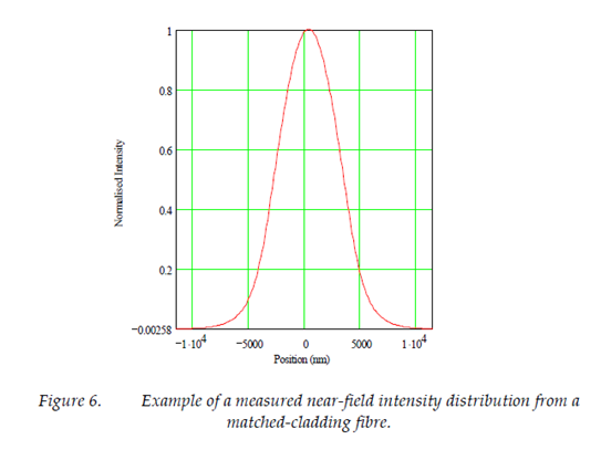
An example of a measured near-field from a standard matched-cladding fiber is shown below in Figure 6.


