ANSI/TIA/EIA 942 Data Center Design Guidelines and Structured Cabling Standards
>> The Purpose of ANSI/TIA/EIA-942
TIA/EIA 942 is the telecommunications infrastructure standard for data centers. The list below shows its purpose:
1. The purpose of this standard is to provide requirements and guidelines for the design and installation of a data center or computer room.
2. It is intended for designers who need a comprehensive understanding of the data center design including the facility planning, the cabling system, and the network design.
3. It facilitates the planning for data centers to occur earlier in the building development process (architectural, facilities, and IT).
Data centers support a wide range of transmission protocols. Some of these protocols impose distance restrictions that are shorter than those imposed by this standard. When applying specific transmission protocols, consult standards, regulations, equipment vendors, and system service suppliers for applicability, limitations, and ancillary requirements. Consider consolidating standardized and proprietary cabling into a single structured cabling system.
The ANSI/TIA/EIA-942 standard specifies:
1. Cabling Design
2. Network Design
3. Facilities Design
4. Informative annexes containing “best practices” and availability requirements
5. Spaces
6. Pathways
7. Racks/cabinets
>> Data Center Cabling Infrastructure
The basic elements of the data center cabling system structure are the following:
- Horizontal Cabling
- Backbone Cabling
- Cross-connect in the entrance room or main distribution area
- Main Cross-Connect (MC) in the main distribution area
- Horizontal Cross-Connect (HC) in the telecommunication room, horizontal distribution area or main distribution area
- Zone outlet or consolidation point in the zone distribution area
- Outlet in the equipment distribution area
>> Hot and Cold Aisles
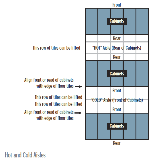
Cabinets and racks shall be arranged in an alternating pattern, with fronts of cabinets/racks facing each other in a row to create “hot” and “cold” aisles.
Cold aisles are in front of racks and cabinets. If there is an access floor, power distribution cables should be installed here under the access floor on the slab.
Hot aisles are behind racks and cabinets. If there is an access floor, cable trays for telecommunications cabling should be located under the access floor in the hot aisles.
A minimum of 1m (3 feet) of front clearance shall be provided for installation of equipment. A front clearance of 1.2m (4 feet) is preferable to accommodate deeper equipment.
A minimum of 0.6m (2 feet) of rear clearance shall be provided for service access at the rear of racks and cabinets. A rear clearance of 1m (3 feet) is preferable. Some equipment may require service clearances of greater than 1m (3 feet).
>> Horizontal Cabling
The horizontal cabling is the portion of the telecommunications cabling system that extends from the mechanical termination in the equipment distribution area to either the horizontal cross-connect in the horizontal distribution area or the main cross-connect in the main distribution area.
The horizontal cabling includes horizontal cables, mechanical terminations, and patch cords or jumpers, and may include a zone outlet or a consolidation point in the zone distribution area.
The following partial listing of common services and systems should be considered when the horizontal cabling is designed:
- Voice, modem and facsimile telecommunications service
- Premises switching equipment
- Computer and telecommunications management connections
- Keyboard/Video/Mouse (KVM) connections
- Data communications
- Wide Area Networks (WAN)
- Local Area Networks (LAN)
- Storage Area Networks (SAN)
- Other building signaling systems (building automation systems such as fire, security, power, HVAC, etc.)
>> Backbone Cabling
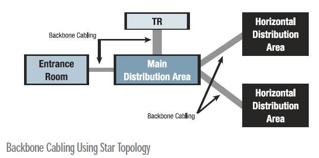
The function of the backbone cabling is to provide connections between the main distribution area, the horizontal distribution area and entrance facilities in the data center cabling system.
Backbone cabling consist of the backbone cables, main cross-connects, horizontal cross-connects, mechanical terminations and patch cord or jumper used for backbone-to-backbone cross-connection.
>> Recognized Cabling Media for Horizontal and Backbone Applications
Recognized cables, associated connecting hardware, jumpers, patch cords, equipment cords and zone area cords shall meet all applicable requirements specified in ANSI/TIA/EIA-568-C.2 and ANSI/TIA/EIA-568-C.3.
- 100 ohm twisted-pair cable (ANSI/TIA/EIA-568-C.2, Category 6 recommended (ANSI/TIA/EIA-568-C.2-1)
- Multimode optical fiber cable, either 62.5/125um or 50/125um (ANSI/TIA/EIA-568-C.3), 50/125um 850nm laser optimized multimode fiber is recommended (ANSI/TIA/EIA-568-C.3-1)
- Single mode optical fiber cable (ANSI/TIA/EIA-568-C.3)
- The recognized coaxial media are 75 ohm (734 and 735 type) coaxial cable (Telcordia Technologies GR-139-CORE) and coaxial connector (ANSI T1.404).
>> Redundancy
Data centers that are equipped with diverse telecommunications facilities may be able to continue their function under catastrophic conditions that would otherwise interrupt the data center’s telecommunications service.
This standard includes four tiers relating to various levels of availability of the data center facility infrastructure. The tiers are related to research conducted by the Uptime Institute, which define four tiers of performance as defined in the following table.
Providing redundant cross-connect areas and pathways that are physically separated can increase the reliability of the communications infrastructure.
It is common for data centers to have multiple access providers providing services, redundant routers, redundant core distribution and edge switches.
Although this network topology provides a certain level of redundancy, the duplication in services and hardware alone does not ensure that single points of failure have been eliminated.
>> Purpose of the ISO 11801:2002 Standard
The International Standard provides:
- Users with an application independent generic cabling system capable of supporting a wide range of applications
- User with a flexible cabling scheme so that modifications are both easy and economical
- Building professionals (for example architects) guidance on the accommodation of cabling at the initial stages of development
The International Standard specifies a multivendor cabling system which may be implemented with material from single and multiple sources, and is related to:
- International standards for cabling components developed by committees in the IEC
- Standards for the installation and operation of information technology cabling as well as for testing of installed cabling
- Applications developed by technical committees of the IEC
- Planning and installation guides which take into account the needs of specific applications
Generic cabling defined within this International Standard:
- Specifies a cabling structure supporting a wide variety of applications
- Specifies channel and link classes A,B,C,D, and E meeting the requirements of standardized applications
- Specifies channel and link classes E and F based on higher performance components to support future applications
- Specifies optical channel and link classes OF-300, OF-500 and OF-2000
- Involves component requirements and specifies cabling implementations that ensure performance of permanent links and channels that meet or exceed the requirements for cabling classes
The International Standard specifies a generic cabling system that is anticipated to have a usable life in excess of 10 years.


