Sumitomo Lynx Splice-On Connector Detailed Installation Instruction
This procedure describes the installation of Sumitomo Lynx CustomFit Splice-On 2mm & 3mm jacket fiber connectors, both UPC polish and APC polish.
:: Sumitomo Splice-On Connector Specifications
Fiber Type: 9/125um Single mode fiber, 50/125um multimode fiber and 62.5/125um multimode fiber
Fiber Cable Jacket Type: 2mm & 3mm
Connector Type: SC
Insertion Loss: <0.3dB (both UPC & APC polish types)
Return Loss: <-40dB (UPC), <-60dB (APC)
Color: Blue (UPC), Green (APC)
:: Sumitomo Splice-On Connector Components
1. Ferrule
2. Outer Housing
3. Inner Housing
4. Spring
5. Rear Housing
6. Crimp Ring
7. Strain Relief (Boot)
8. Protection Tube
9. Fiber Protection Sleeve
:: Required Connector Installation Tools
1. Sumitomo Electric SOC Crimp Tool
2. 3mm or 2mm Cordage Slitter
3. Kevlar Snips
4. Fiber Optic Strippers
5. Connector Holder & Cordage Holder
6. Fusion Splicer
7. Fiber Optic Cleaver
:: Sumitomo Lynx-CustomFit Splice On Connector Procedure
1. Remove housing-side covering from package
2. Insert the cordage through assembly parts
3. Insert cordage into appropriate groove (2mm or 3mm) of slitter using back of tool as stopping point.
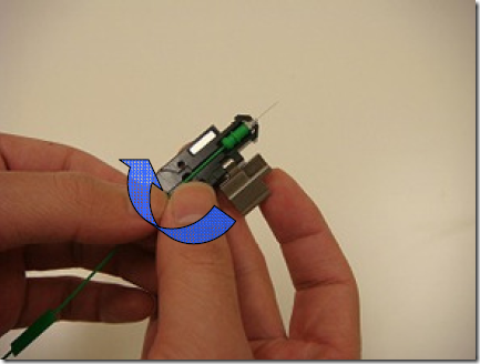
4. Spin the slitter while holding the cordage creating a ring cut.
5. Pull the cord to remove the outer jacketing.
6. Pull the Kevlar to remove excess slack inside cord.
7. Insert cordage into appropriate groove (2mm or 3mm) of slitter using the back of tool as stopping point.
8. Using the back of the tool as a gauge, mark the fiber. This mark represents the ending strip point and reference point for the fiber holder edge.
9. While holding the tool, pull the cordage slitting the jacket in the process.
10. Fold the Kevlar and sheathing back.
11. Insert the fiber through the fiber protection sleeve.
12. Strip the fiber coating to the marked point.
13. Clean the fiber.
14. Check for fiber breaks by gently snapping the end.
15. Set the fiber into the holder curl side down.
16. The 900 micron coating should be flush with the edge of the fiber holder.
17. Set the fiber holder into the fiber cleaver.
18. Slide the front tip of the holder until it touches cleaver.
19. Close the cover of the fiber cleaver, cutting the glass fiber.
20. Place the holder into the fusion splicer from behind the v-groove.
21. Remove the ferrule side covering of the package. (open just before using the ferrule subassembly).
22. Insert the ferrule/fiber into holder and close the cover. Ensure that the glass fiber does not hit the holder.
23. Insert this holder into fusion splicer from behind the v-groove.
24. Close the fusion splicer’s cover.
25. Ensure that the fusion splicer is set for single fiber splicing and 60mm sleeve setting.
26. Complete the splice.
27. Open the ferrule holder. Remove the fiber from the splicer while maintaining tension on assembly to prevent bending.
28. Move the protection sleeve into position adjusting the sleeve by slanting the fiber.
29. DO NOT twist the ferrule subassembly or fiber. Sleeve should cover metal flange.
30. Center the fiber protection sleeve inside heater and complete the heat cycle.
31. After completing of heater cycle allow the assembly to cool at least 1 minute before removing.
32. Remove the tape from the outer sheath of the cordage and spread Kevlar.
33. Separate the crimp ring then slide the spring and rear housing up until they touch the back of the ferrule subassembly.
34. Pull the Kevlar and sheathing out from the rear housing.
35. Holding the metal screw of the fiber stub, remove the dust cap without pulling on fiber protection sleeve.
36. The ferrule should fit inside the key when using APC connectors align the red marks with each other.
37. Loose press the ferrule subassembly into the notched housing.
38. Gently press the dust cap onto the ferrule. The dust cap is being using as a temporary holder.
39. Align the groove and slide the inner housing over the rear housing until the components lock together.
40. Snap the string from the dust cap.
41. Divide the Kevlar into two tight bundles.
42. Spread the sheath and Kevlar around the rear housing.
43. While maintaining the position of the sheath and Kevlar, slide the protection tube down 1/4 inch above rear of housing.
44. Slide the crimp ring over the protection tube keeping sheath and Kevlar split.
45. Slide crimp ring until it touches rear of rear housing.
46. The larger diameter of the crimp tool (noted by red dot) should face the rear housing.
47. Crimp the crimp ring with the crimp tool. Be careful not to crimp the black part of the rear housing.
48. Rotate the connector by 90 degrees, and crimp again.
49. cut off excess Kevlar using snips.
50. Put the outer housing over the inner housing. Align the notch of the outer housing with the notch of inner housing.
51. Align the boot with the notch of the outer housing. Slide the rear boot until it stops.
52. Complete.
53. Connector Cleaning.
It is recommended to keep the dust cap installed to maintain cleanliness and to prevent end-face damage before installation.
We recommends at a minimum following a simple wet dry connector cleaning procedure. The procedure will require using a lint free wipe in conjunction with 99% pure isopopyl alcohol being used as a cleaning solvent.
Dampen a small area of the wipe with alcohol. Staring on the dampened side the of the wipe, move the connector end-face from the wet area to the dry area in a single motion. Rotate the connector 90 degrees and repeat the process on clean section of the wipe.


