Corning Spider Fan Out Kit Field Installation Instruction
1. General
1.1
This procedure describes the recommended installation procedure for Corning Cable Systems Spider Fan-Out Kits (Plus) for non-armored cables containing up to 24 fibers (Figure 1). Fan-Outs permit the branching of fibers contained in an optical cable into individual cables, which can then be connectorized or terminated per system interface requirements.
1.2
Two sizes of Spider Fan-Out kits are available for MIC® cables; one unit accommodates 4 to 12 fibers, a larger unit has a 14 – 24 fiber capacity. The larger Fan-Out body is also used for all loose tube cable applications. Both units are available in single mode (yellow fan-out tubing) and multimode (orange fan-out
tubing) versions.
1.3
As described in this procedure, each of the individual fibers is fed into a factory-assembled insert plug which incorporates 1-meter (39.37 in.) lengths of furcation tubing. Figure 1 identifies the components of the Fan-Out kits.
1.4
This issue reflects the introduction of Gel-free buffer tubes.
3. Tools and Materials
3.1
The following tools and materials are required to install a Spider Fan-Out kit:
- Scissors
- Utility knife with hook blade
- Lint-free tissues
- Tape measure
- Fiber-Clean® cleaning wipes if filling compound is present
- Buffer tube stripper
- Number tags
- 200 μm No-Nik® tool
- Alcohol
- Small Phillips head and slotted screwdrivers
- Emery cloth
- Sheath ripper
- Adjustable wrench
4. Cable Preparation
4.1
Follow the appropriate section below for the type of cable you are installing: steps 4.2 through 4.10 for loose tube cable or steps 4.11 through 4.16 for MIC cable.
:: Loose Tube Cable
4.2
Select the proper size components for the cable being terminated:
- bushing insert (for small diameter cables only )
- flat washer
- sheath clamp
Use the one which provide the closest possible fit. The kit for loose tube cables can be installed on cables ranging in OD from 8.6mm (0.339 in.) to 15.7 mm (0.618 in.)
4.3
Slide the compression nut, bushing insert (if needed), flat washer, and sheath clamp over the end of the cable and slide them 1.75 m (69 in.) down the cable (Figure 2).
4.4
Refer to the stripping procedure appropriate for the loose tube cable you are using. Prepare the loose tube cable as shown in Figure 3.
4.5
To prepare a loose tube cable:
a) Separate the yarn from the cable core and trim the yarn flush with the end of the cable sheath.
b) Cut the central member to a length of 45 mm (1.8 in.)
c) Carefully separate and remove the buffer tubes with a buffer stripping tool to a length of 20 mm (0.75 in.).
4.6
If the buffer tube is Gel-free, carefully cut out the water block yarns and proceed to step 4.7. If not, clean the individual fibers with Fiber-Clean wipes until the fibers are absolutely free of residue.
4.7
Clean the end of the cable sheath for a length of about 5 cm (2 in.) to ensure a dry, clean surface for the cable clamp.
4.8
If the cable clamp is a tight fit on the cable, slide the clamp to a point 6 mm (0.25 in.) from the end of the cable sheath (see Figure 4).
Note: If the sheath clamp has a loose fit on the cable, it will be pushed into place inside the body by the compression nut and bushing insert in step 5.4.
4.9
Remove 1.25 cm (0.5 in.) of the outer coating of the central member, if present (Figure 4).
4.10
Proceed to step 5.1.
:: MIC Cable
4.11
Select the proper size components for the MIC cable being terminated:
- bushing insert (for small diameter cables only )
- flat washer
- aramid yarn crimp (consisting of a ring and wedge)
Use the components which provide the closest possible fit. There are two kits for MIC cables:
- for fiber counts of 4-12, the cable O.D. range is 6.5 mm (0.256 in.) to 12.9 mm (0.508 in.)
- for fiber counts of 13 to 24, the cable O.D. range is 11.5 mm (0.453 in.) to 15.7 mm (0.618 in.).
4.12
Slide the compression nut, bushing insert (if needed), flat washer, and the ring portion of an aramid yarn crimp over the end of the cable and slide them 1.25 m (50 in.) down the cable (Figure 5). Note that the arrow on the ring must point towards the end of the cable.
4.13
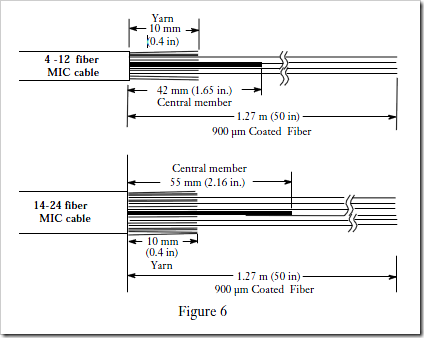
Refer to SRP-004-024, Sheath Removal Procedure for Siecor Single Layer MIC Cables. Strip the cable components to the lengths shown in Figure 6. To prepare the cable:
- Separate the yarn from the 900 μm fibers and trim the yarn to 10 mm (0.4 in.)
- Carefully cut the central member to the lengths shown in Figure 6.
- If present, remove 19 mm (0.75 in.) of any coating from the end of the central member.
4.14
Using the hook blade knife, carefully make two cuts on opposite sides of the cable sheath end: for 4-12 fiber cables the cuts should be 8 mm (0.3 in); for 14-24 fiber cables, make the cuts 15 mm (0.6 in.) long (Figure 7).
4.15
Slide the wedge portion of the aramid yarn crimp over the fibers. Slide the wedge under the the aramid yarn and cable sheath as shown in Figure 8.
4.16
Slide the ring over the the end of the cable sheath so that the split end of the sheath and aramid yarn is caught between the parts (Figure 9).
5. Fan-Out Assembly for Loose Tube Cable and MIC Cable Kits
5.1
Prepare the body of the fan-out by slipping an O-ring into place as shown in Figure 10 (a large fan-out body is shown).
5.2
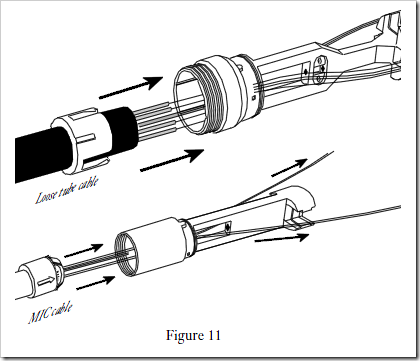
Route the cable through the fan-out body as follows:
- Feed the individual fibers through the fan-out body as shown in Figure 11.
- Once the fibers have passed through the barrel of the fanout body, route half of the fibers on each side body.
- Slide the cable into the barrel of the fan-out body until the sheath clamp or aramid yarn crimp is fully seated.
Observe the following special considerations during this step:
- Make sure that the “keys“ of the loose tube sheath clamp are aligned with the slots inside the body- rotate the clamp on the cable if necessary (see Figure 14).
- Make sure that the central member is seated inside the hole inside the body (see Figure 12)
- Route all of the fibers from a buffer tube on the same respective side of the fan-out body.
5.3
If you are installing a 14-24 fiber Fan-Out body, secure the central member by placing the two clamp plates in their recesses on opposite sides of the body. Secure the plates with screws as shown in Figure 12.
5.4
Slide the compression nut, bushing insert (if present) and the washer against the barrel of the fan-out body. Thread the nut into or onto the barrel of the fan-out body until it is hand-tight (Figure 13). Use an adjustable wrench to tighten the compression nut.
5.5
Slide the shell of the fan-out over the fan-out insert plugs (Figure 14). Move the shell down the furcation tubes so that it is out of the way.
5.6
Prepare the connector ends of the furcation tubing of each insert plug as described in the installation procedure supplied with the connector you are using. Cut the inner tubing with a sharp utility knife. Make sure the tubing is “open” and “round” at each cut.
5.7
Install the fibers in the insert plugs as follows:
- Carefully feed the individual fibers into the furcation tubing openings in the first insert plug.
- Feed one fiber at a time and place a number tag on the tubing as the fiber comes out the other end (Figure 15).
- As you feed in the fibers, make sure there that are no crossovers.
- After completing the first plug, secure it in the clip in the fan-out body (Figure 16).
- Repeat steps a-d until all the fibers have been installed (Figure 17).
5.8
Slide the shell into place over the body of the fan-out. Secure the shell to the fan-out body with the two screws provided (Figure 19). Install the connectors according to the manufacturer’s instructions.
6. Reentry
6.1
If you have an unsuccessful connectorization attempt, it may be necessary to reenter the spider fan-out. If this is the case:
- Trim off the bad connector.
- Remove the screws and shell from the furcation.
- Pull the appropriate fiber back about 5 cm (2 in.) (Figure 20).
- Trim the fan-out tube by the amount of bare fiber required for your connector.
- Push the fiber back into the fan-out tube.
- Reinstall the shell over the fiber body.
- Install the new connector according to its manufacturer’s instructions.


