Terminating a Corning Field Installable SC connectors
Corning field installable SC connectors feature a pre-radiused Zirconia ferrule. This pre-radiused ferrule makes high quality field termination possible.
This tutorial describes the fiber optic cable termination process (hand polishing process) of a Corning field-installable SC connector (PC finish). The fiber optic termination kit described here comes from Corning Cable Systems. Please follow the manufacturer’s instruction if you are more familiar with fiber termination kit from other manufacturers.
Although this tutorial describes the steps for fiber optic termination of a Corning SC connector, the concept applies to all epoxy and polish connectors.
The major fiber optic termination steps are summarized as follows:
3. Inject epoxy/adhesive into connector ferrule
4. Insert fiber into connector
6. Cure epoxy/adhesive with oven
7. Cleave excess fiber from ferrule tip
Fiber optic termination tools used in this tutorial
- Fiber optic safety glasses
- Fiber disposal unit (fiber disposal bottle)
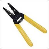
- 3mm fiber jacket stripper
- Aramid yarn cutter (Kevlar cutter)
- A pair of regular scissors
- Permanent marker
- Miller fiber stripper
- Fiber optic cleaning kit including lint-free wipes, alcohol dispensing bottle, isopropyl alcohol , compressed air, etc
- Epoxy mixer
- 3-cc epoxy injection syringe
- SC connector crimp tool
- Ruby fiber scribe tool
- Epoxy curing oven with thermometer and fiber stand
- Fiber optic polishing kit, including glass plate, polishing pad, SC connector polishing puck, 12um air polish lapping film, 5um rough polishing lapping film, 1um fine polishing lapping film, etc.
- Fiber optic inspection microscope with 200X magnification level
Precautions
- Always wear your safety glasses. Glass fiber pieces are very sharp and dangerous
- Prevent epoxy/adhesive contact with skin or eyes
- Promptly dispose glass fiber pieces into fiber disposal bottle or on a loop of tape
- Never directly look into a fiber. The invisible laser light can damage your eyes
Components of a Corning’s field-installable SC connector (for 3mm jacketed cable)

Step 1: Fiber Cable Preparation
- Slide the 3mm strain relief boot onto the cable end to be terminated

- Per connector manufacturer’s instruction, use jacket stripper (2.0mm hole) to remove fiber jacket to specified length and expose the aramid yarn. (the Kevlar)
- Trim the aramid yarn to specified length with scissors according to the spec.

Fiber jacket and aramid yarn stripped to specified length per connector manufacturer’s spec


Aramid yarn cutter (Kevlar cutter)
- Fold the aramid yarn back and slide the crimp ring onto the cable, keep folding the aramid yarn back with the crimp ring.

- Use a permanent marker to mark specified length from end of the jacket per manufacturer’s spec on fiber tight buffer.

- Strip the buffer in 5mm increments up to the mark with your preferred buffer and coating stripper.

Strip the buffer with a No-Nik 200um fiber stripper

Miller triple holes fiber stripper - Strips 250um to 125um, 900um to 250um and 2~3mm Jacket Removal
- Clean the stripped fiber with a link-free wipe soaked in isopropyl alcohol and put it aside for later use. (Be careful not to contaminate the cleaned fiber!)

Step 2: Epoxy/Adhesive Preparation
- Here we use Tra-Con BAF253 Bipax package as the epoxy sample, please follow your epoxy manufacturer’s epoxy preparation procedure.
- Open the divider of the Bipax package, and roll the epoxy package on a flat surface with the epoxy mixer to mix the epoxy. When the epoxy changes to a consistent color throughout, the epoxy is ready.

Open the divider of the Bipax epoxy package

Tra-Con BAF253 fiber optic epoxy

Epoxy mixer for Bipax packaged epoxy
- Remove the plunger from the 3-cc epoxy syringe, cut one corner of the Bipax epoxy package, and pour the epoxy into the syringe. Replace the plunger back into the syringe.
- Use an inexpensive regular scissors to cut the package. DO NOT use the aramid yarn cutter! The aramid yarn cutter will be ruined if contaminated by epoxy.
- Try not to trap air in the syringe when pouring the epoxy, air bubbles can cause voids during epoxy curing.

Pouring epoxy into the 3-cc syringe

A 3-cc epoxy syringe popular in fiber optic connector termination
- Hold syringe vertically with the needle up. Let the epoxy run to the bottom. Slowly move the plunger up, forcing out the air.
- Wipe the epoxy that squirts out of the needle with a wipe.

Step 3: Inject Epoxy/Adhesive into Connector Ferrule
- Take a connector, remove and throw away the cap from the rear of the assembly since you won’t need it any more.
- Remove the dust cap from the connector ferrule (front of the assembly) and keep it. You will need it to protect the finished connector.
- Hold the connector with ferrule pointed up; insert the syringe into the connector guiding tube until it stops in the connector.
- Slowly push the plunger to inject epoxy into the connector body, stop once you see epoxy bead appears at the tip of the ferrule, and remove the syringe.


Step 4: Insert Fiber into Connector
- Slide the fiber into the connector all the way back to the jacket. As you feed the fiber into the connector, rotate the connector back and forth so epoxy gets spread all around the fiber and keeps the fiber to the center of the hole in the ferrule.


Step 5: Crimp Connector
- Slide the crimp ring back down the cable jacket, away from the connector, to free the aramid yarn. Use tweezers to spread the aramid yarn evenly around the back of the connector body.
- Slide the crimp ring back towards the connector over the aramid yarn until it stops against the wall of the crimp body.

- Place the connector assembly into your crimper tool hex, make sure the cable jacket is under the crimp ring, and squeeze the crimper tool’s handles shut to crimp the connector. Remove the connector from the crimper tool.

- Slide 3mm strain relief boot over the crimp ring. The connector is now ready for next step.

Step 6: Cure Epoxy/Adhesive with Oven
- Check the temperature of the epoxy curing oven with the thermometer, and make sure the temperature is 125~130°C (or curing temperature per your epoxy manufacturer’s spec)
- You should have turned on the oven before cable preparation so it would have enough time to warm up and stabilize at 125°C
- Put the connector assembly into the curing oven, and cure the epoxy for 6 minutes.
- Make sure you don’t break the fiber protruding from the ferrule tip. You will have to start over if you break the fiber since it always breaks inside the ferrule which makes polishing impossible.

Curing connector epoxy with an oven (note the thermometer and timer)

Connector epoxy curing oven with a thermometer
- Take out the connector after epoxy curing; allow it to cool down for next step.
Step 7: Cleave Excess Fiber from Ferrule Tip
- Hold the connector with ferrule tip pointed up; nick the excess fiber at a point 0.15~0.2mm from where it exits the epoxy bead with a ruby fiber scribe.


- Pull the fiber to break it and dispose the fiber piece into a fiber disposal bottle or onto a loop of tape. Now the connector is ready for polishing.


Step 8: Ferrule Polishing and Cleaning
- NOTE: DO NOT OVER-POLISH in each stage. Over-polish can create fiber undercutting resulting expensive rework and product replacement.
- Prepare the fiber optic polishing glass plate, pad and lapping film as follows
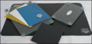

- Place a rubber polish pad on the glass plate.
- Clean the polish pad with lint-free wipes soaked in isopropyl alcohol, followed by a dry lint-free wipe clean and a compressed air blow.
- Place a 5um grit lapping film (gray color in this example) with the adhesive backing down on the polish pad. Place a connector polishing puck on the lapping film.
- Place a 1um grit lapping film (white color in this example) with adhesive backing down on the polish pad. Place another connector polishing puck on the lapping film.
- Using each polishing puck on its corresponding polishing film will prevent contamination of the 1um grit lapping film.
- Drop distilled water onto each lapping film appropriate the size of a quarter, and uniformly wet the surface of each film with its corresponding polishing puck.
- Air polish the fiber stub with 12um lapping film
- Hold the connector as shown. Take a 12um lapping film and fold it into a U-shape with the abrasive side facing the connector.
- Gently polish the fiber stub by making 2~3cm circles on the abrasive side of the film.
- Stop when you see that the fiber stub no longer scratches the lapping film. You can also notice the change in sound as the fiber stub gets filed down and the epoxy bead is removed.
- NOTE: DO NOT OVER-POLISH! The optimum fiber height is 100um above the ferrule.
- Check the condition of the connector end-face. A small amount of epoxy should be present.
- Clean the connector tip with distilled water, followed by lint-free wipe soaked in isopropyl alcohol.

- Rough polishing the connector on 5um lapping film
- Now hold the polishing puck for the 5um film in the air and then insert the connector. The connector ferrule should move freely and seat on the polishing puck top. Never insert the connector into the puck while it is lying on the glass because you may chip the glass at the ferrule tip.

- Now put the polishing puck on the 5um film, and gently make one or two figure 8 polishing patterns with very light pressure. The purpose is to make sure that the fiber stub is flush with the epoxy bead.

- Once the fiber stub is flush with the epoxy bead, make 4 to 5 figure 8 polishing patterns with medium pressure. Check the epoxy bead after each figure 8 pattern.
- Once the epoxy bead is almost gone, remove and clean the connector with a dry lint-free wipe.
- Another indication for this step is that the polishing suddenly feels slippery. It will feel like the polishing puck is floating on air.

- Fine polishing the connector on 1um lapping film
- Now put the connector into the polishing puck for the 1um (white color) lapping film as shown in the 5um polishing puck step.
- Make about 10 figure 8 polishing patterns on the 1um film with almost no pressure. Actually just enough to hold the connector steady.
- DO NOT use too much pressure or the connector will not polish.
- Remove the connector and clean the connector end-face and ferrule surfaces with a lint-free wipe soaked in isopropyl alcohol.
- Finish the cleaning with a dry lint-free wipe followed by a blow of compressed air.

Step 9: Final Inspection
- Insert the connector into the end of your fiber optic inspection microscope with at least 200X magnification. You need the correct ferrule adapter for your connector. FC, SC and ST connectors need 2.5mm ferrule adapter for the fiber optic inspection microscope. LC connector needs a 1.25mm ferrule adapter instead.

- Passing criteria for hand polishing fiber optic connector
- The ferrule end-face should have a mirror finish with the edge of the fiber face perfectly circular
- No epoxy/adhesive should be visible
- Light scratches and small pits are acceptable if they are not on the fiber core. However shattered fiber, cracked fiber and heavily pitted fibers are not acceptable.
- If the connector passes visual inspection then you can put on the dust cap over the connector ferrule.

good quality fiber optic connector termination
Step 10: Trouble Shooting Tips for Fiber Optic Cable Termination
-
Causes of shattered fibers
- Excessive oven curing temperatures during epoxy cure
- Wrong excess fiber scribing and removal methods
- Accidental fiber breakage before or after fiber scribing
- Excessive pressure in the air polish step (12um lapping film)
- Excessive pressure in the rough polishing step (5um lapping film)
-
Causes of cracked fibers
- The same reasons listed in the shattered fibers list
- The 5um rough polishing lapping film is worn out
- Causes of heavily pitted fibers
- Excessive polishing on the 5um lapping film