Complex Amplitudes of a Monochromatic Beam in Isotropic and Homogeneous Medium
When a light beam propagates in an isotropic and homogeneous medium, the beam can be represented by its electric field E(r,t), which can be written:
E(r,t) = A cos(ωt - k • r) (1)
where A is a constant vector representing the amplitude, ω is the angular frequency, k is the wave vector (wave number), and r is the position in space.
For mathematical simplicity, the monochromatic plane wave in (1) is often written:

Note:
Only the real part of the right side represents the actual electrical field. This is the analytic representation only.
For the purpose of describing various representations of the polarization states, we consider propagation along the z axis. Since light wave is a transverse wave, the electric field vector must lie in the xy plane (perpendicular to z the propagation axis).
The two mutually independent components of the electric field vector can then be written as:

Without loss of generality, we consider the time evolution of the electric field vector at the origin z = 0. Thus (3) becomes:

By using (2) as its representation (exponential format), (4) becomes:

Here we define the term Complex Amplitudes Ex and Ey as:

The polarization state of a light beam can be described in terms of the amplitudes(Ax, Ay) and the phase angles (δx,δy) of the x and y components of the electric field vector.
Thus, all the information about the polarization state of a wave is contained in the complex amplitudes in (6).
Jones Vector Representation
The background for Jones Matrix Calculus
The description of the polarizing behavior of the optical field in terms of amplitudes was one of the first great success of the wave theory of light. The solution of the wave equation in terms of transverse components leads to elliptically polarized light and its degenerate linear and circular forms.
On the basis of the amplitude results, many results could be understood (e.g., Young's interference experiment, circularly polarized light). However, even using the amplitude formulation, numerous problems become difficult to treat, such as the propagation of the field through several polarizing components.
To facilitate the treatment of complicated polarization problems at the amplitude level, in 1941, R. Clark Jones developed a matrix calculus for treating these problems, commonly called the Jones matrix calculus.
The Jones calculus involves complex quantities contained in 2x1 column matrices (the Jones vector) and 2x2 matrices (the Jones matrices).
As a general rule, the most approximate choice of matrix method is to use the Jones calculus for amplitude superposition problems and the Mueller formalism for intensity superposition problems.
Jones Vector
In Jones vector, the plane wave of (5) is expressed in terms of its complex amplitudes as a column vector:

Note that the Jones vector is a complex vector; that is, its elements are complex numbers.
E is not a vector in the real physical space; rather, it is a vector in an abstract mathematical space.
To get the real x and y components of the electric field, we must perform the real part operation:

The Jones vector specifies the polarization state of the wave uniquely. It contains complete information about the amplitudes and the phases of the electric field vector's x and y components.
Normalized Jones Vector
In the Jones vector (7), the maximum amplitudes Ax and Ay are real quantities. The presence of the exponent with imaginary arguments causes Ex and Ey to be complex quantities.
Before we proceed to find the Jones vectors for various states of polarized light, we discuss the normalization of the Jones vector; it is customary to express the Jones vector in normalized form.
The total intensity I of the optical field is given by:

where

Ex* and Ey* are complex conjugate for Ex and Ey respectively.
Equation (9) can be obtained by the following matrix multiplications:

The row matrix [Ex* Ey*] is the complex transpose of the Jones vector (column matrix E) and is written as E†; thus,

So the total intensity I:

will bring us:

It is customary to set E02 = 1, whereupon we say that the Jones vector is normalized.
Thus the normalized condition for equation (10) can be written as:

Note:
Jones vector can ONLY be used to describe COMPLETELY polarized light.
Jones Vectors for Some States of Completely Polarized Light
1. Linear horizontally (x axis) polarized light
For this state, Ey = 0, so (7) becomes:

From the normalization condition (14) we see that Ax2 = 1. Thus, suppressing eiδx because it is unimodular, the normalized Jones vector for linearly horizontally polarized light is written:

2. Linear vertically (y axis) polarized light.
Ex = 0, so Ay2 = 1 and

3. Linear + 45° polarized light.
Ex = Ey, so 2Ax2 = 1 and

4. Linear - 45° polarized light.
Ex = - Ey, so 2Ax2 = 1 and

5. Right-hand circularly polarized light.
For this case, Ax = Ay and δy - δx = + 90°. Then 2Ax2 = 1 and

6. Left-hand circularly polarized light.
For this case, Ax = Ay and δy - δx = - 90°. Then 2Ax2 = 1 and

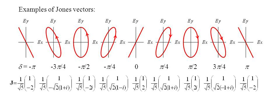
7. Other examples:

Since the Jones vector is a column matrix of rank 2, any pair of orthogonal Jones vectors can be used as a basis of the mathematical space spanned by all the Jones vectors.
Any polarization state can be represented as a superposition of two mutually orthogonal polarization states  and
and  , or R and L.
In particular, we can resolve the basic linear polarization states  and
and  into two circular polarization states R and L and vice versa.
These relations are given by:

Circular polarization states are seen to consist of linear oscillations along the x and y directions with equal amplitude  , but with a phase difference of
  .
.
Similarly, a linear polarization state can be seen as a superposition of two oppositely sensed circular polarization states.
Orthonormal Property
Two vectors A and B are said to orthogonal if their dot product equals 0

Or in complex notation,
A† B = 0
If this condition is met, we say that the Jones vectors are orthogonal.
Examples:
1. Linear horizontally polarized light A (x axis) and linear vertically polarized light B (y axis)
We use A† B and find that

so these two states are orthogonal or, since we are using normalized vectors, orthonormal.
2. Right-hand circularly polarized light A and left-hand circularly polarized light B
Again using A† B and we find that

Combining Orthonormal Condition and Normalizing Condition into One Single Equation
From last section's discussion, we find that the orthonormal condition for two Jones vectors E1 and E2 is

And let's recall that the normalizing condition for Jones vectors is shown in equation (14) (where sub i = j)

So we can combine these two conditions and write them into one single equation:

δij is called the Kronecker delta and has the property

Superpose of Coherent Amplitudes
Jones vector can only describe completely polarized light which means the light beams are coherent.
On the other hand, another vector representation called Stokes vectors can represent partially polarized and unpolarized lights.
Stockes vectors can be used for the superposition of incoherent intensities. Similarly, we can superpose coherent amplitudes, that is, Jones vectors.
For example, the Jones vector for horizontal polarization is EH and that for vertical polarization is Ev, so that

Adding EH and Ev and then we get

Equation (26) is the Jones vector for elliptically polarized light.
Thus, superposing two orthogonal linear polarizations give rise to elliptically polarized light.
Example 1:
If Ax = Ay, δx = δy, then from (26) we can get

(27) is the Jones vector linear +45° polarized light.
(27) can also be be obtained by superposing (16) (linear horizontally polarized) and (17) (linear vertically polarized)

(28) is identical to (18) except the normalizing factor.
Example 2:
We can superpose left and right circularly polarized light of equal amplitudes. Then, from (20) and (21), we get:

(29) is the Jones vector for linear horizontally polarized light just as (16), except of the normalizing factor.
Example 3:
The superposition of two opposite (right handed and left handed) circularly polarized lights of unequal amplitudes.
From (20) and (21), we have two opposite polarized lights with amplitude a and b respectively.

By superposition (vector addition), we get the resultant Jones vector:

From (30), we get the x and y components as:

Note:
By Euler's formula,

We can now restore the propagator ωt - kz of time (t) and position (z), so (31) can be written as:

Taking the real part of (32), we have:

Thus we get:

Squaring and adding these two equations in (34) together and we get:

Equation (35) is the equation of an ellipse whose major axis length is (a+b) and minor axis length is (a-b).
Thus we get the conclusion:
The superposition of two oppositely circularly polarized lights of unequal magnitudes gives rise to a (non-rotated) ellipse with its locus vector moving in a counterclockwise direction.