We have discussed how fiber dispersion limits the performance of fiber-optic communication systems by broadening optical pulses as they propagate inside the fiber. Fiber loss is another fundamental limiting factor as it reduces the average power reaching the receiver. Since optical receivers need a certain minimum amount of power for recovering the signal accurately, the transmission distance is inherently limited by fiber loss. In fact, as discussed earlier, the use of silica fibers for optical communications became practical only when the loss was reduced to an acceptable level to achieve a transmission distance of 10 km or more. This tutorial is devoted to a discussion of various loss mechanisms in optical fibers.
1. Attenuation Coefficient
Under quite general conditions power attenuation inside an optical fiber is governed by
dP/dz = - αP
where α is the attenuation coefficient and P is the optical power. Here α includes not only material absorption but also other sources of power attenuation. If P is the power launched at the input of a fiber of length L, the output power Pout is given by
Pout = Pinexp(-αL)
It is customary to express α in units of dB/km by using the relation

and refer to it as the fiber loss.
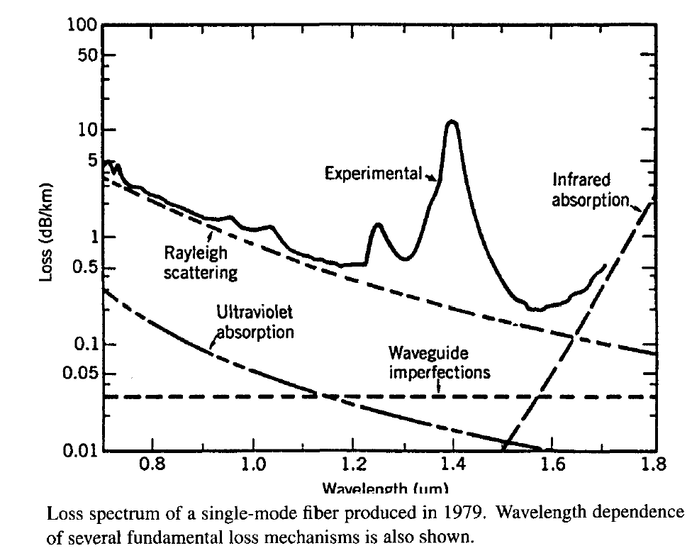
Fiber loss depends on the wavelength of transmitted light. The following figure shows the loss spectrum α(λ) of a single-mode fiber with 9.4-μm core diameter, Δ = 1.9 x 10⁻³, and 1.1-μm cutoff wavelength.

This fiber exhibits a loss of only about 0.2 dB/km in the wavelength region near 1.55 μm, the lowest value realized in 1979. This value is close to the fundamental limit of about 0.15 dB/km for silica fibers. The loss spectrum also exhibits a strong peak near 1.39 μm and several other smaller peaks. A secondary minimum is found to occur near 1.3 μm, where the fiber loss is below 0.5 dB/km. Since fiber dispersion is also minimum near 1.3 μm, this low-loss window is often used for optical communication systems. The loss is considerably higher for shorter wavelengths and exceeds 5 dB/km in the visible region of the optical spectrum. Several factors contribute to the loss; their relative contributions are also shown in the figure. The two important among them are material absorption and Rayleigh scattering.
2. Material Absorption
Optical fibers are made of fused silica. Material absorption can be divided into two categories. Intrinsic material absorption corresponds to the loss caused by pure silica, whereas extrinsic absorption is related to the loss caused by impurities. Any material absorbs at certain wavelengths corresponding to the electronic and vibrational resonances associated with specific molecules. For silica (SiO2) molecules, electronic resonances occur in the ultraviolet region (λ < 0.4 μm), whereas vibrational resonances occur in the infrared region (λ > 7 μm). Because of the amorphous nature of fused silica, theses resonances are in the form of absorption bands whose tails extend into the visible region. The above figure shows that intrinsic material absorption for silica in the wavelength range 0.8-1.6 μm is below 0.1 dB/km. In fact, it is less than 0.03 dB/km in the 1.3-1.6 μm wavelength window commonly used for lightwave systems.
Extrinsic material absorption results from the presence of impurities. Transition-metal impurities such as Fe, Cu, Co, Ni, Mn, and Cr absorb strongly in the wavelength range 0.6-1.6 μm. Their amount should be reduced to below 1 part per billion (<10-9) to obtain a loss level below 1 dB/km. Such high-purity silica can be obtained by using modern techniques. The main source of extrinsic absorption in sate-of-the-art fibers is the presence of water vapors. A vibrational resonance of the OH ion occurs at 2.73 μm. Its harmonic and combination tones with silica produce strong absorption at the 1.39-, 1.24-, and 0.95-μm wavelengths. The three spectral peaks seen in the figure occur near these wavelengths and are due to the presence of residual water vapor in silica. Even a concentration of 1 part per million can cause a loss of about 50 dB/km at 1.39 μm. Typically, OH ion concentration should be reduced to below 10-8 to obtain the loss below 10 dB/km at this wavelength and realize a low-loss fiber with a loss spectrum of this figure. Dopants such as GeO2, P2O5, and B2O3 used during fiber fabrication to produce the required index step can also lead to additional losses.
In a new kind of fiber, known as the dry fiber, the OH concentration is reduced to such low levels that the 1.39-μm peak almost disappears. The following figure shows the loss and dispersion profiles of such a fiber (OFS AllWave fiber). Such fibers can be used to transmit WDM signals over the entire wavelength range of 1.3 to 1.65 μm.

3. Rayleigh Scattering
Rayleigh scattering is a fundamental loss mechanism arising from local microscopic fluctuations in density. Silica molecules move randomly in the molten state and freeze in place during fiber fabrication. Density fluctuations lead to random fluctuations of the refractive index on a scale smaller than the optical wavelength λ. Light scattering in such a medium is known as Rayleigh scattering The scattering cross section varies as λ-4 and is dominant at short wavelengths. The intrinsic loss of silica fibers from Rayleigh scattering can be written as
αR = C/λ4
where the constant C is in the range 0.7-0.9 (dB/km)-μm4 depending on the constituents of the fiber core. These values of C correspond to αR = 0.12-0.16 dB/km at λ = 1.55 μm, indicating that fiber loss in the figure above is dominated by Rayleigh scattering near this wavelength.
The contribution of Rayleigh scattering can be reduced to below 0.01 dB/km at longer wavelengths near 3 μm. Silica fibers cannot be used in this wavelength region, since infrared absorption begins to dominate the fiber loss beyond 1.6 μm. Considerable effort has been directed toward finding other suitable materials with low absorption beyond 2 μm. Fluorozirconate (ZrF4) fibers have an intrinsic material absorption of about 0.01 dB/km near 2.55 μm and have the potential for exhibiting loss smaller by one order of magnitude compared with silica fibers; state-of-the-art fluoride fibers, however, exhibit a loss of about 1 dB/km because of extrinsic losses. Chalcogenide and polycrystalline fibers exhibit minimum loss in the far-infrared region near 10 μm. The theoretically predicted minimum value of fiber loss for such fibers is below 10-3 dB/km because of reduced Rayleigh scattering even though current loss levels are higher by several orders of magnitude.
4. Waveguide Imperfections
An ideal single-mode fiber with a perfect cylindrical geometry guides the optical mode without energy leakage into the cladding layer. In practice, imperfections at the core-cladding interface (e.g., random core-radius variations) can lead to additional losses which contribute to the net fiber loss. The physical process behind such losses is Mie scattering occurring due to index inhomogeneities on a scale longer than the optical wavelength. Care is generally taken to ensure that the core radius does not vary significantly along the fiber length during manufacture. Such variations can be kept below 1% and the resulting scattering loss is typically below 0.03 dB/km.
Bends in the fiber constitute another source of scattering loss. The reason can be understood by using the ray picture. Normally, a guided ray hits the core-cladding interface at an angle greater than the critical angle to experience total internal reflection. However, near a bend the angle decreases and may become smaller than the critical angle for tight bends. The mode energy is scattered into the cladding layer. The bending loss is proportional to exp(- R/Rc), where R is the radius of curvature of the fiber bend and Rc is given by Rc = a/(n12 - n22). For single-mode fibers Rc = 0.2-0.4 mm typically, and the bending loss is negligible (< 0.01 dB/km) for bend radius R > 5 mm. Since most macroscopic bends exceed R = 5 mm, macrobending losses are negligible in practice.
A major source of fiber loss, particularly in the cable form, is related to random axial distortions which invariably occur during cabling when the fiber is pressed against a surface that is not perfectly smooth. Such losses are referred to as microbending losses and have been extensively studied. Microbends cause an increase in the fiber loss for both multimode and single-mode fibers and can result in an excessively large loss (~ 100 dB/km) if precautions are not taken to minimize them. For single-mode fibers, microbending losses can be minimized by choose the V parameter as close to the cutoff value of 2.405 as possible so that mode energy is mostly confined to the core In practice, the fiber is designed to have V in the range of 2-2.4 at the operating wavelength. Many other sources of optical loss exist in a fiber cable. These are related to splices and connectors used in forming the fiber link and are often treated as a part of the cable loss; microbending losses can also be included in the total cable loss.
The loss mechanisms discussed in this tutorial are power independent. Optical fibers also exhibit nonlinear losses which become important at high power levels. These are discussed in the next tutorial.