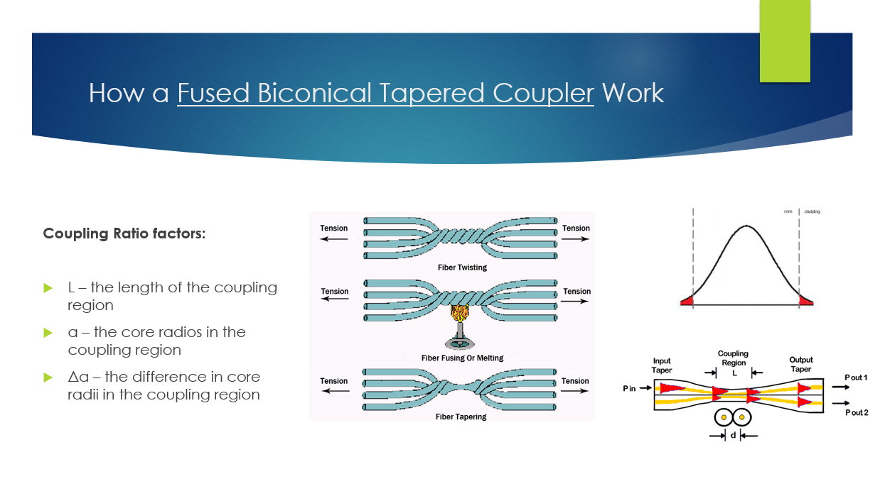
A fused fiber optic coupler is a structure formed by two fibers. The two fibers are placed side to side, twisted, put in a flame, heated up, and then drawn longer and become fused together. Within each fiber, there is a long tapered section, then a uniform section of length L where they are fused together, and then another positive taper back to the original fiber size.
There is light power exchange between the fibers in the fused coupling region. During the drawing process, the output power are monitored and the process can be stopped at any desired coupling ratio. The coupling takes place through interaction between the two cladding modes. During the operation, the power output values from the output ports are monitored, and the process can be stopped at any desired coupling ratio.
The working principle is based on the leaking and coupling of evanescent wave. An evanescent wave is shown in this picture. An evanescent wave is a near-field wave with an intensity that decays exponentially as a function of the distance from the boundary. The red tails are the evanescent wave.
In the fused biconical coupler process, the cores of the two parallel fibers are so close to each other that the evanescent waves can leak from one fiber into the other fiber. The energy transfer is dependent on the core separation distance d and the interaction length L.
If the coupling region is long enough, a complete energy transfer can take place from one fiber into the other. If the length is still longer, the process will continue, shifting the energy back into the original fiber core.
The tapers are very gradual, so that a negligible fraction of the optical power from either input ports is reflected back, almost all of the power gets coupled to the two output ports. It is for this reason that these devices are sometimes called directional couplers.
Using this technique, many different types of couplers can be made that uses the fact that the optical power coupled from one fiber to the other can be controlled by changing the three factors:
- L, the length of the coupling region. In this coupling region, the lightwave fields from the two fibers interact and get coupled back and forth.
- d, the core separation distance in the coupling region
- Δa, the difference in core radii in the coupling region
Here is the concept of coupling length. The light in fiber A couples to the core of fiber B. The light power level transmitted depends on coupling length. Light from fiber A will couple 100%; that is, it will pass entirely into fiber B after a certain distance called the coupling length or odd multiple of the coupling length.
The coupling length varies with the wavelength of the light. This fact that the coupling length depends on the wavelength of the light in a single mode coupler makes it possible to make a Wavelength Division Multiplexer/Demultiplexer.
Let’s imagine that we transmit two wavelengths along a fiber such as 1.3µm and 1.55µm. The coupling length for 1.55µm is greater than the coupling length of 1.3µm. This results in the 1.3µm light couples 100% into fiber B, then back to the fiber A. Also the 1.55µm couples 100% to fiber B. By carefully selecting the coupling length, it is possible to combine or separate two wavelengths. This is shown in the second picture. This type of coupler is called a Wavelength Division Multipler/Demultiplexer.