Looking for an optical fiber power meter?
We have them in stock!
Order it here or by clicking on the picture below.

The working principle of calibrating an optical power meter
An optical power meter is the most common type of test equipment used to support fiber optic system. NIST developed a testing system to provide absolute power calibrations for optical power meters.
These measurements are accomplished using either collimated-beam or connectorized-fiber configurations at the three principle wavelength regions used by the fiber telecommunication industry: 850, 1310, and 1550nm.
Most optical power meters in use today are based on diode sensors made of either silicon, germanium or indium gallium arsenide. The output responses of these sensors are highly dependent on the wavelength of the incident electromagnetic radiation.
As shown in a NIST study, optical power meters that have been calibrated with a collimated beam can exhibit significant errors when used with a connectorized fiber. This effect is predominantly due to the radiation that is reflected from the detector (or window) surface back onto the fiber/connector assembly and then back into the detector. This reflected power causes the power meter to read higher than the power meter without a connector attached. The magnitude of this error is a function of both wavelength and connector type, and, as a result, the power meter should be calibrated with the same fiber and connector with which it is to be used.
NIST optical power measurement traceability is based on the C-series calorimeter, a laser energy reference standard. The calorimeter is used, in turn, to calibrate a transfer standard using a calibrated beamsplitter system and various laser sources. The transfer standard is then used for the optical power meter calibrations.
The transfer standard is a thermal detector which has a black, highly absorbent coating and thus is spectrally insensitive over the wavelength regions of interest for optical power meter calibrations. The low reflectance surface of the transfer standard allows it to be used for both parallel beam and connectorized fiber measurements. This transfer standard is used with a system composed of laser diodes, fibers, connectors, fiber splitters, monitor detectors, and lenses to calibrate optical power meters. The measurement system is designed to accommodate most commonly used connector and fiber types.
Primary Reference Standard
The C-series calorimeter was designed to measure the electromagnetic radiation produced by CW (continuous wave) laser sources in the power range 1 mW to 1 W at wavelengths ranging from ultraviolet to the near infrared. The calorimeter was constructed to accommodate the unique characteristics of laser radiation (nonuniform profiles, temporal and spatial coherence, for example). The calorimeter has a relatively simple geometrical structure, and thus its behavior can be analyzed in a straightforward manner from first principle of thermodynamics and linear system analysis.
The fundamental mechanism of the calorimeter is the complete absorption of the laser radiation with subsequent conversion of the electromagnetic energy to thermal energy. The temperature increase which results from this energy absorption is then used to determine the electromagnetic energy in the laser beam.
The energy absorption takes place in a cylindrical cavity which is surrounded by a massive temperature-controlled jacket. Thermocouples whose junctions are bonded to both the absorbing cavity and the surrounding jacket produce a thermoelectric voltage proportional to the temperature difference between these two structures. An electrical heater wire is located in the absorbing cavity to provide a means to calibrate the cavity electrically. The calorimeter was designed to maximize the equivalence between electrical and laser energy.
Transfer Standard
The device presently used as a transfer or laboratory standard for optical power calibrations is a commercially available, electrically calibrated pyroelectric radiometer (ECPR).
This device was originally designed and built by NIST scientists. The pyroelectric sensor is made of lithium tantalate covered with gold-black. The gold-black coating (about 1µm thick) is pure gold is deposited under specific temperature and pressure onto the lithium tantalate surface.
When correctly deposited in this manner, the gold forms small, interwoven strands which trap incident light and thus make the gold surface appear black. Gold-black is a common absorber material and is approximately 99% absorbent in the visible and near infrared regions.
Pyroelectric sensors produce an electrical voltage proportional to temperature rate of change; as a result, the laser energy incident on the detector must be modulated or pulsed in order to use this type of detector to measure CW radiation.
The detector used here has a chopper wheel which is placed in front of the pyroelectric sensor and is used to "chop" the beam into pulses at a rate of 15 Hz. Because pyroelectric materials are also piezoelectric, the chopper wheel must be placed at least 30 cm from the sensor to eliminate the effects due to the acoustic vibrations created in the air by the spinning wheel. In addition, any other vibration sources should be removed, or at least their effects should be minimized.
The ECPR is used as a laboratory standard in many optical power calibration laboratories because
- It is sensitive to low power radiation
- It is relatively spectrally flat
- It has a low reflectance surface in the 600 - 1600 nm wavelength region
This type of ECPR is normally used in the 10 - 1000 µW power range, which is in the range of primary importance in optical power calibrations. Below 10 µW the output becomes too noisy to use reliably.
However, the ECPR has two major disadvantages:
- Non-uniformity of response across the detector surface
- The fragility of the gold-black coating
A potential error source associated with the ECPR is the variation of the detector response from radiation striking different spots on the detector surface.
Figure 1 shows a uniformity scan performed on a NIST ECPR using a beam 1.3 mm in diameter (between 1/e2 points) at a wavelength of 845nm.

This non-uniformity is typical of pyroelectric detectors and is presumably due to non-uniformity of the pyroelectric material thickness. Scientists at NIST have since developed a more uniform pyroelectric detector which provides more accurate measurements.
Before the ECPR is used as a transfer standard, it is first calibrated against the C-series calorimeters at wavelengths of 632.8, 825, 1064, 1319, and 1523 nm using the C-series beamsplitter system.
The beamsplitter is made of sapphire and has no optical coatings. A small angle of incidence (≈1°) of the incident beam relative to the beamsplitter minimizes the effects of polarization changes and small changes in the angle of incidence itself.
The ECPR is placed in the first reflected beam, and the C-series calorimeter is placed in the main transmitted beam. The beamsplitter is calibrated at each wavelength for which it is used. These calibrations are done by using two C-series calorimeters to measure the power ratio of the two beams. Additionally, the beamsplitter ratio is checked (one or two runs) before using each laser source for power meter calibration measurements.
A computer-controlled shutter is used to regulate the exposure time of the two instruments (the C-series calorimeter and the ECPR) during the measurement. When the shutter is open and the laser energy is incident on the two detectors, voltage readings from both instruments are recorded. The C-series voltage information is used to determine the energy incident on the calorimeter; then given the beamsplitter ratio, the energy incident on the ECPR can be calculated. The average power is found by dividing the energy by the exposure time. A calibration factor is then calculated by dividing the ECPR reading by the incident power.
The errors due to the non-uniformity of the ECPR sensor can be minimized by using the same beam diameter for both the C-series measurements and the power meter calibration.To assure that a constant beam diameter is always used, we employ a laser beam profile instrument to measure beam diameter at the detector. A beam diameter of 3 mm (at the ECPR sensor surface) is normally used for these measurements.
Tunable Laser Diode
To minimize measurement errors associated with the source wavelength and the detector spectral responsivity, tunable laser sources are installed int he measurement system.
The gain medium of the tunable laser is a conventional laser diode but the internal Fabry-Perot resonator is disabled by an anti-reflection coating on one of the facets. An external cavity is created by adding an external diffraction grating which acts both as a mirror and a wavelength-selective element. The output power, single-mode operation, and wavelength stability strongly depend on temperature stability. Collimating lenses, shown in Figure 2, are used to collect the divergent laser beam. Since the beam diverges as much as 45°, the lenses must have a numerical aperture (N.A.) of 0.4 and have surfaces whose wavefront aberrations are less than λ/4, where λ is the wavelength of the laser radiation.

The cavity design includes a side-mode filter which suppresses undesired side modes. The filter is a narrowband wavelength filter which has better wavelength selectivity than a diffraction grating alone.
Adjustment of the external cavity to achieve a specific wavelength consists of selecting an angular position of the grating and an angular position of the etalon. These is a simple relationship between the angle of the grating relative to the incoming beam and the wavelength that will be reflected back to the laser chip:
λ = 2a*sin(α)
where α is the angle between the incident beam and the grating normal, a is the spacing between grooves, and λ is the incident wavelength.
Figure 3 shows that the laser wavelength depends on the position or step number of the grating motor; this function must be known during the calibration.

Figure 4 depicts the optical spectrum of the 1300nm tunable laser diode at three settings. The two extreme spectrum lines correspond to two extreme wavelengths that the laser is capable of producing. The output power is a function of wavelength.

Figure 5 shows the power spectrum of the 1300nm tunable laser diode.

Optical Power Measurement System
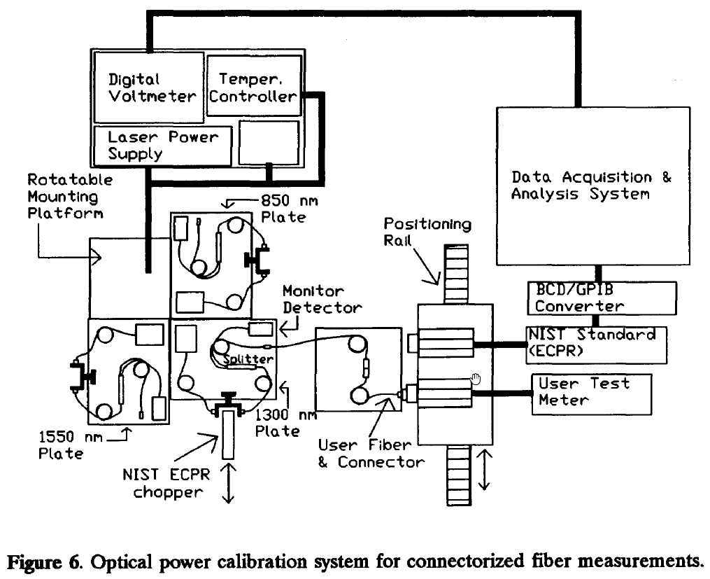
Figure 6 shows the configuration of the system used for connectorized fiber measurements during the calibration of optical fiber power meters. The ECPR transfer standard is used as the reference for these calibrations.

The system contains several laser source plates, a connector converter stage (for connectorized measurements), lenses (for parallel beam measurements), and a positioning stage for comparing the ECPR and the meter being calibrated.
An enlarged view of a laser source plate is shown in Figure 7.

All the optical fibers in the system are single mode, whereas the customer's fiber may be either single mode or multimode.
Each plate contains a laser diode whose output is transmitted to a fiber splitter from which about 5% of the power is diverted to a monitor and about 1% of the power to the optical spectrum analyzer. The remaining power is transmitted through a fiber to the meter being calibrated.
All fibers are securely fixed so that they will not move during the measurement. As shown in Figure 7, a "U" shaped collimator is positioned in the propagation path following each diode laser. This collimator contains two lenses which provide a collimated beam for the ECPR chopper wheel. When the chopper wheel is inserted into the space provided by this fixture, a chopped beam is then incident onto the detectors (the monitor and the ECPR).
A special sample-and-hold current-to-voltage converter is used for the monitor output. This converter stores the voltage reading from the chopped signal until the digital voltmeter takes a reading.
Each time the ECPR is used for measurements in this system, the chopper wheel is inserted into the collimator opening and is removed when the ECPR is not being used.
For collimated beam measurements, a lens at the end of the fiber path provides a parallel beam to the ECPR and test meter. For connectorized measurements, the customer's fiber is coupled to the measurement system fiber using a connectorized-fiber jumper located on a connector converter stage.
The first step in a calibration measurement is the determination of power in either the collimated beam or from the end of a fiber, whichever is appropriate. For this measurement, either the ECPR is placed in the path of the parallel beam or else the customer's fiber is connected to the ECPR using appropriate adapters.
In either case, both the ECPR readings and the monitor voltages are recorded. Then the ECPR is moved and replaced by the test meter. For connectorized-fiber measurements, the fiber connector is moved from the ECPR to the test meter. The test meter readings and the monitor voltages are then recorded.
The absolute power going to the test meter is established by the average ECPR power readings. Power changes (due to diode laser instability) are taken into account by the monitor readings. Thus, this method relies on the stability of the splitter ratio, not on its actual value (unlike C-series calorimeter).
Figure 8 depicts measured responsivity of a germanium detector in the 1550 nm region using this tunable laser system. Five data points were taken (and averaged) for each wavelength point on the graph.

Conclusion
This is a calibration system based on tunable laser diodes. With this system, optical power meters can be calibrated both at a particular source wavelength or over the range of wavelengths of the tunable laser diode.
This system is a useful addition to the existing calibration system which is restricted to fixed laser wavelengths.