Table of of Contents
- What are fiber optic visual fault locators (VFL)?
- Other names of a VFL
- How to use a VFL
- VFL applications
- Types of VFLs
- VFL powers, distances and eye safety
- VFL spec sheet
- Top product brands
- VFL maintenance
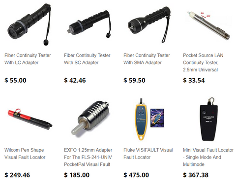
We stock all types of visual fault locators.
Order here or by clicking on the picture below.
What are fiber optic visual fault locators?
Many of the problems in connection of fiber optic networks are related to making proper connections. Since the light used in systems is invisible infrared light (IR) beyond the range of the human eye, one cannot see the system transmitter light.
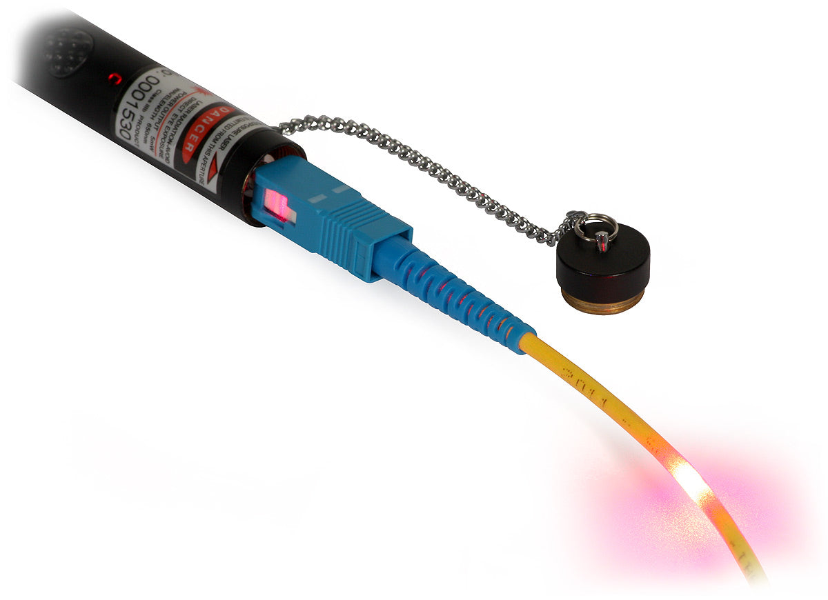
A Visual Fault Identifier (VFI) or Visual Fault Locator (VFL) is a visible light source (incandescent bulb, LED or laser diode) that injects visible light energy into a fiber.


By injecting the light from a visible source, one can visually trace the fiber from transmitter to receiver to ensure correct orientation and check continuity besides.
Sharp bends, breaks, faulty connectors and other faults will "leak" the light allowing technicians to visually spot the defects.
The VFI/VFL is an ideal tool for locating a large number of defects that occur at connection points in and around fiber cabinets which are hidden in an OTDRs "blind-spot" or dead-zone.
Fosco Connect offers VFI units for both single-ferrule and multi-ferrule connector styles.
Note:
Some cable materials can absorb red light. Standard 3 mm yellow and orange patch leads generally provide good visibility. Many purple/gray/black cables do not.
Other names of visual fault locators
There are many other names for visual fault locator, such as:
- Fiber Tracers
- Visual Fault Finder
- Visual Fault Indicator
- Visual Fault Identifier
- Visual Fault Detector
- Visual Fault Light
- Visual Fault Locator Pen
How to use a fiber optic visual fault locator?
A visual fault locator emits a bright beam of red light easily visible from a distance. Connect it to one end of a fiber then locate that fiber at the other end, even if it is one of many fibers either in a cable or terminated in a rack.
Perform simple end-to-end continuity checks. Verify the proper polarity and orientation of fibers within a multi-fiber connector like the MT-RJ.
A visual fault locator can quickly illuminate fiber breaks, damaged connectors on patch cords, defective splices in splice trays, and tight fiber bends in and around equipment racks.
The choice of a continuous wave output mode for steady fault illumination or a flashing output mode makes for easier fault location.
The integrated universal 2.5mm adapter makes for easy connection to SC, ST, FC, and FJ connectors. The optional 1.25mm adapter allows for connection to LC and MU connectors.
Attach the visual fault locator to your belt using a lanyard so it is always on hand when you need it.
Applications of visual fault locators
- Continuity Check (continuity testing)

- Breaks in fiber

- Macrobend loss

- Dirty Connectors

- Faulty splices (mechanical splice and fusion splice)

- Faulty connector crimps
- Poor components or connections
- Complement tool for OTDR (OTDR's dead zone)
- Splice optimization

- Visually identify one fiber in a multi-fiber cable


Types of visual fault locators
-
Visual fault locator pen
Pen-style visual fault locator, with a pocket-size, can be carried anywhere easily.
-
Mini key-chain visual fault locator
The HiLite is a compact but powerful visible red laser source designed to troubleshoot faults or breaks in fiber optic cables.
-
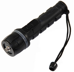
Hand-held visual fault locators
Hand-held visual fault locator is offered in a range of connector bulkheads styles, from universals to specific connector types.


Visual Fault Locator's Powers, Distances and Eye Safety
The useful operating range of fiber optic visual fault locators is widely misquoted, with ranges of 20, 30, 40 and even 50 Km often incorrectly stated.
This is what they will actually do. There is no magic, it's just a combination of emitted power, attenuation and eye sensitivity, combined with eye safety limits on emitted power when no connector is attached (which is often not quoted at all).
| VFL range under ideal conditions | Power level connected | "Connector end view" continuity | "Break location" in patch lead | "Side glow" continuity |
| Class 1 Legal Limit | +3 dBm | 10 Km | 7 Km | 5 Km |
| Class 2M Legal Limit | +10 dBm | 11.2 Km | 8.2 Km | 6.2 Km |
| Illegal VFL "20Km" | +20 mW / 13 dBm | 11.7 Km | 8.7 Km | 6.7 Km |
| Illegal VFL "30Km" | +30 mW / 14.8 dBm | 12 Km | 9 Km | 7 Km |
| Illegal VFL "40Km" | +40 mW / 16 dBm | 12.2 Km | 9.2 Km | 7.2 Km |
| Illegal VFL "50Km" | +50 mW / +17 dBm | 12.4 Km | 9.4 Km | 7.4 Km |
Visual fault locator spec sheet example
| Light source: | Class II laser diode |
| Central wavelength: | 650nm +/- 10nm |
| Spectral width (FWHM): | < 5nm |
| Laser light pulse duration: |
Continuous in CW mode |
| Operation environtment: | -10°C to +50°C, 0 to 95% RH (non-condensing) |
| Storage environment: | -20°C to +80°C, 0 to 95% RH (non-condensing) |
| Power supply: | Two 1.5V AA Alkaline batteries |
| Connector: | 2.5mm universal |
| Battery life: | > 80 hours |
Top brands in the industry
-
Fluke Networks

-
JDSU (now named Lumentum/Viavi)


-
Ideal Industries


Visual fault locator maintenance
Cleaning all connectors before coupling them to a visual fault locator.
Users should always cover the output port with the dust cap when the instrument is not in use.
If binding or stickiness is felt when inserting connectors into the output port, the ceramic sleeve should be cleaned
To clean the sleeve, insert a one-click cleaning gun into the output port until it stops. Twist the wand, remove it, and discard.
Do not reuse the cleaning wand. Do not blow air into the output port to remove dirt particles. Doing so will only pack the dirt and make it harder to remove.
We keep in stock all types of visual fault locators.
Order here or by clicking on the picture below.