After the fiber cables are installed and terminated, it’s time for testing. You will need to test for continuity, end-to-end loss and then troubleshoot the problems.
If it is a long outside plant cable with intermediate splices, you will probably want to verify the individual splices with an OTDR, since that’s the only way to make sure that each one is good.
In this article, we will introduce the most common types of fiber optic testers and their respective applications with videos showing the usage of each type.
Types of fiber optic testers and their applications
- Fiber identifers
- Light sources and power meters
- Connector inspection (microscopes)
- OTDR
- Spectrum Analyzers
- Visual fault locators
We supply all types of fiber optic testers. Order it here!
:: What are fiber identifiers?
An optical-fiber identifier, also known as a live fiber detector or optical-fiber detector, is a non-intrusive tool that detects optical transmissions, or the lack thereof, in an optical fiber.

Order Fiber Identifiers from Fosco
The optical-fiber identifier appears to be a simple device but is actually technically sophisticated. The technician clamps the device onto a fiber and receives an indication of traffic direction, presence (or absence) of modulation and, on some units, a core power reading. Because the identifier can make these measurements rapidly, the technician can quickly assess the viability of the fiber system without time-consuming equipment setups.
An optical-fiber identifier is an invaluable aid with which an installer can perform the following functions:
- Identify live or dark fibers
- Verify continuity through splices and connectors
- Identify signal direction (transmit or receive)
- Trace signals with the use of tone generators
- Other applications, such as relative-loss measurements, fiber identification for routing, and general installation and troubleshooting.
Basically, the identifier samples the light by a process known as macrobending, where the fiber is bent around a precise radius that allows light to leak through the cladding and protective coverings into detectors.
This small amount of light is then amplified, processed by the identifier and indicated on the front panel of the device. The goal is to sample as small a signal as possible to minimize insertion loss.
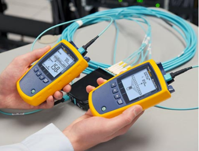
:: What are light sources and power meters?
The most basic fiber optic measurement is optical power from the end of a fiber. This measurement is the basis for loss measurements as well as the power from a source or presented at a receiver.

Order light sources and power meters from Fosco
Typically both transmitters and receivers have receptacles for fiber optic connectors, so measuring the power of a transmitter is done by attaching a test cable to the source and measuring the power at the other end.
For receivers, one disconnects the cable attached to the receiver receptacle and measures the output with the meter.

Optical power meters typically use semiconductor detectors since they are sensitive to light in the wavelengths and power levels common to fiber optics. Most fiber optic power meters are available with a choice of 3 different detectors, silicon (Si), Germanium (Ge), or Indium-Gallium-Arsenide (InGaAs).
:: How to do connector inspection with a microscope?
It is a fact that fiber end-face contamination is a major cause of network outages and downtime. Fiber inspection microscopes enable network technicians and other personnel to safely inspect fiber endfaces for contamination and verify the effectiveness of fiber cleaning procedures.

Order fiber connector inspection microscopes from Fosco
Fiber microscopes with integrated protective infrared filters can minimize the risk of viewing a live fiber. There are also video inspection products with no direct optical path between fiber and the users eye. These products employ a video signal path (like a camcorder viewfinder) and convert the optical image to a safe, high resolution video image.
:: What is an OTDR (Optical Time-Domain Reflectometer)?
An OTDR is the optical equivalent of an electronic time domain reflectometer. It injects a series of optical pulses into the fiber under test and extracts, from the same end of the fiber, light that is scattered (Rayleigh backscatter) or reflected back from points along the fiber.

The scattered or reflected light that is gathered back is used to characterize the optical fiber. This is equivalent to the way that an electronic time-domain meter measures reflections caused by changes in the impedance of the cable under test. The strength of the return pulses is measured and integrated as a function of time, and plotted as a function of fiber length.
The common types of OTDR-like test equipment are:
-
Full-feature OTDR:
- Full-feature OTDRs are traditional, optical time domain reflectometers. They are feature-rich and usually larger, heavier, and less portable than either the hand-held OTDR or the fiber break locator.
- Often a full-feature OTDR has a main frame that can be fitted with multi-function plug-in units to perform many fiber measurement tasks. The full-feature OTDR often has a greater measurement range than the other types of OTDR-like equipment. Often it is used in laboratories and in the field for difficult fiber measurements.
-
Hand-held OTDR and Fiber break locator:
- Hand-held (formerly mini) OTDRs and fiber break locators are designed to troubleshoot fiber networks in a field environment, often using battery power.
- Hand-held OTDRs are commonly used to measure fiber links and locate fiber breaks, points of high loss, high reflectance, end-to-end loss, and Optical Return Loss (ORL).
- Fiber break locators are intended to be low-cost instruments specifically designed to determine the location of a catastrophic fiber event, e.g., fiber break, point of high reflectance, or high loss. The fiber break locator is an opto-electronic tape measure designed to measure only distance to catastrophic fiber events.
:: What are optical spectrum analyzers (OSA)?
As we know RF spectrum analyzer is used to view and diagnose RF signals over frequency bands. Here X-axis is electromagnetic radio frequency and Y-axis is the power.

Order optical spectrum analyzer (OSA) from Fosco
Similarly for measurement of optical signal, optical spectrum analyzer(OSA) is needed. It is basically an optical instrument. It measures properties of light over range of electromagnetic spectrum. The measured variable of OSA is usually light intensity. It can also be polarization state.

The main application of OSA is to troubleshoot problems in DWDM systems.

This figure depicts simple block diagram of Optical Spectrum Analyzer. Let us understand functions of each of the modules of OSA.
- Incoming optical signal to be measured is passed through wavelength tunable filter. This optical filter resolves different spectral components individually.
- Photodetector converts optical signal into electrical equivalent signal. This electrical current magnitude is proportional to incident optical power.
- The current is converted into equivalent voltage using transimpedance amplifier.
- Later this is digitized using ADC converter in the Optical Spectrum Analyzer. This signal is applied to vertical part of display unit as amplitude.
- Ramp tunes optical filter such that its resonant wavelength is proportional to horizontal position.
Optical Spectrum Analyzer Vendors
There are different Vendors of Optical Spectrum Analyzer (OSA). It include YOKOGAWA, Keysight Technologies, Thorlabs, Anritsu, Finisar, EXFO, APEX technologies etc.
:: What are visual fault locators?
Many of the problems in connection of fiber optic networks are related to making proper connections. Since the light used in systems is invisible infrared light (IR) beyond the range of the human eye, one cannot see the system transmitter light.

Order visual fault locators from Fosco
By injecting the light from a visible source, such as a LED, laser or incandescent bulb, one can visually trace the fiber from transmitter to receiver to ensure correct orientation and check continuity besides. The simple instruments that inject visible light are called fiber tracers or visual fault locators.

Continuity testing is useful to test a few fibers in a cable before installation or to determine if a terminated cable has been damaged.To test for continuity, attach the fiber to the fiber optic tracer or VFL. If light is visible at the far end, the fiber is not damaged.
Tracing Fibers
One of the best uses for these devices is to trace fibers for identification or to determine correct connections. To trace fibers using the fiber optic tracer or VFL, connect the fiber to the output connector of the unit. The light output will be visible to the eye at the other end of the fiber. This allows finding particular fibers in multifiber cables easily for proper connections during installation.