When system requirements are not critical, the LED is the preferred light source. But for long-distance links or high bit rate links (above 155 Mbps), laser diodes are required.
There are several types of laser diodes:
- Multi-longitudinal mode (MLM) or Fabry-Perot laser
- Single longitudinal mode laser (SLM)
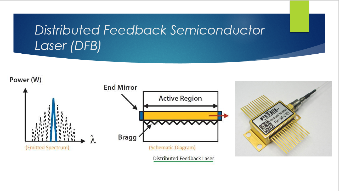
- Single longitudinal mode with distributed feedback laser, usually called a DFB laser
- DFB laser with external modulator
- Vertical-cavity surface-emitting laser (VCSEL)
These laser types were developed in this chronical order. We will now go into a little detail of each type.
The MLM or Fabry-Perot laser emits a multimode emission pattern as shown in this figure. The output of an MLM laser has a dominant spectral line on the desired wavelength and subsidiary lines separated by about 1nm that have some lesser amplitudes.
As the laser is modulated, the subsidiary modes are modulated as well. The full width at half-maximum (FWHM) of the laser is about 4~5 nm when modulated.
When we examine MLM laser spectrum more closely, we find out that even though the total output power is relatively stable, there can be significant variation in the power of each individual mode. This phenomenon is called mode partitioning, and it has important effects on the application of MLM lasers.
When the laser signal is transmitted over fiber with wavelength-dependent group delay (also called chromatic dispersion), mode partitioning gives rise to noise in the output signal. This introduces a power-independent error rate floor into the system response which cannot be overcome by making allowances in the system power budget. With systems operating at data rates higher than a few hundred Mbps, this noise can put a major limit to the fiber link distance.
Another drawback is that even small reflections back into the laser from external surfaces (such as connectors) can cause significant change in the mode partitioning behavior and thus the performance of the system.
SLM lasers are designed such that cavity losses are different for different longitudinal modes of the cavity, in contrast with the MLM whose losses are independent.
In the SLM laser the longitudinal mode with the smallest cavity loss reaches threshold first and becomes the dominant mode. The other nearby modes are discriminated against by their high losses, which prevent buildup from spontaneous emission. In this case, the power carried by these subsidiary modes is usually of low level, less than 1% of the total emitted power.
Etalon is an additional short optical cavity inserted into the laser optical cavity. Etalon is composed of two mutually parallel surfaces.
The distance between the two surfaces is about the size of the gain curve of the laser. Thus, only one longitudinal mode is under the gain curve each time, as shown in this figure - choosing single longitudinal mode with an etalon.
There are two optical cavities inside the laser with etalon. Longitudinal mode can exist in the double cavity structure only if it simultaneously fulfill the conditions of standing wave for both cavity lengths.
The linewidth of the etalon longitudinal mode is determined by the reflection of its surfaces. The higher the reflection, the narrower the longitudinal mode of the etalon.
When an SLM is operating properly, we can expect the first side mode to be at least 30 dB down from the dominant mode.
DFB laser structure has built-in wavelength selectivity by means of a feedback mechanism. The feedback is not localized at the facets but is distributed throughout the cavity length.
This type of laser contains a periodic grating between the two layers of the laser structure (typically at the interface n-InP substrate and n-InGaAsP layers) to provide feedback at a fixed wavelength that is determined by the grating pitch.
A DFB laser is very sensitive to light feedback, particularly from the connector where the laser interfaces with the fiber link. Even a relatively small amount of feedback – for instance, less than 0.1% - can destabilize the laser and affect system performance.
Several steps can be taken to reduce the intensity of the feedback or to reduce the effects of the feedback. One step is to use antireflective coatings. Feedback can also be reduced by using angle polished (APC) connectors. Another more effective step is to install an isolator between the laser and the fiber connector.
An important parameter of a DFB laser is the Mode Suppression Ratio (MSR). The main goal of DFB laser is to reduce subsidiary longitudinal modes and to obtain maximum power in the dominant mode. We need a MSR to be greater than 30 dB for a DFB laser to operate continuously.
Our interest here is to transmit a light signal from the laser with a singular narrow spectral line. The FWHM under ideal conditions is less than 0.2nm. When a DFB laser is combined with multiple quantum well (MQW) structures to improve spectral line width, the line width can be down to a few hundred kHz.
As the spectral line width gets larger, chromatic dispersion increases which is highly undesirable for high bit rate systems (above 1 Gbps). The DFB laser has the narrowest line width among practical production-type lasers on the market. It is almost universally used on long-haul fiber optic links.
A DFB laser is expensive and its operation is vital to a fiber optic circuit. To ensure optimum operation of a DFB laser and to monitor its vital operation, several components are added to the DFB assembly. For example, a photodiode monitors its output; a thermoelectric cooler (TEC) or heatpump and heatsink control the junction temperature of the laser chip, and a feedback circuit controls its output and maintains the desired frequency. The ideal temperature for the laser chip is 25°C.
We have been talking about optical sources with direct modulation, sometimes called intensity modulation. All we are doing is turning the laser on and off, where on may represent a binary 1 and off may represent a binary 0.
In reality, the laser is never turned completely off. The equivalent “off” is a point on the laser’s operational curve at just above threshold or just below threshold. This threshold setting is important to reduce chirp.
Another approach to modulating the binary 1s and 0s is to use an optical modulator. The concepts of direct modulation and that of using an optical modulator are shown in this figure. Notice that the optical modulator is located between the laser carrier wave (CW) source and the fiber cable output interface. A Carrier Wave (CW) source is a light source that is “on” all the time at its rated power output.
Optical modulators are integrated components designed to control the amount of continuous optical power transmitted in an optical waveguide. They act like shutters; the shutter is closed for a binary 0 and open for a binary 1.
There are commonly three types of optical modulators:
- Mach-Zehnder (M-Z)
- Electro-refraction
- Electro-absorption (semiconductor) MQM (multiple quantum well)
The Mach-Zehnder (M-Z) modulator is an interferometer that makes use of titanium-diffused LiNbO3 waveguides or a directional coupler configuration. The waveguides in a Mach-Zehnder modulator form a Y-configuration. The refractive index of electro-optic materials such as LiNbO3 can be changed by applying an external voltage.
In the absence of the external voltage, the optical fields in the two arms of the M-Z interferometer experience identical phase shifts and interfere constructively. The additional phase shift introduced in one of the arms through voltage-induced index changes destroys the constructive nature of the interference and reduces the transmitter output. In particularly, no light is transmitted when the phase difference between the two arms equals π, because now it is destructive interference.
As a result, the electrical bit stream applied to the modulator produces an optical replica of the bit stream.
The performance of an external modulator is quantified through the on-to-off ratio, more often called the extinction ratio and modulation bandwidth. LiNbO3 modulators have an extinction ratio greater than 20 dB and can be modulated at bit rates up to 75 Gbps.
Modulators have been fabricated using electro-optical polymers. Here modulation bit rates have been achieved up to 60 Gbps. Such modulators are often integrated monolithically with the driving circuitry.
Another type of modulator is made using semiconductors. These are electro-absorption (EA) modulators. This technique uses the Franz-Keldysh effect, according to which the bandgap of the semiconductor decreases when an electric field is applied across it. Thus, a transparent semiconductor layer begins to absorb light when its bandgap is reduced by applying an external voltage. This is when photon energy exceeds bandgap energy. Because the electro-absorption effect is stronger in MQW (Multiple Quantum Well) structures, MQW has become the structure of choice in this type of modulator. An extinction ratio of 15 dB or more for an applied reverse bias of 2V can be made at a bit rate of several Gbps. Low chirp-rate transmission has been achieved at 5 Gbps. These types of modulators are used on fiber-optic circuits at bit rates greater than 20 Gbps and have been demonstrated up to 60 Gbps.
We re-stress that the basic purpose of using a modulator is to reduce pulse broadening caused by chirp. Many of these modulators are monolithically incorporated on the same chip of the transmitter they control.
The Multi-longitudinal mode (MLM or Fabry-Perot), Single longitudinal mode (SLM), and DFB lasers require electric current on the order of tens of milliamperes to operate. In addition, their output light beam to interface the circular optical fiber has an elliptical cross section, typically with an aspect ratio of 3:1. Such a beam is a bad match of the cylindrical beam capture of the fiber. A noncylindrical light beam often requires additional optics to enhance the coupling capability to a circular cross-section fiber core.
A Vertical-Cavity Surface-Emitting Laser (VCSEL) emits the desired circular light beam. A comparison of these beams are shown in this figure.
A VCSEL consists of a vertical sandwich of p-type multilayer, an active region, and an n-type multilayer. The number of layers depends on the desired wavelength. The multilayers comprise Bragg reflectors that are fabricated with In + Ga + As + (Al or P). For example, an In + Ga + As + P combination is used for lasers in the wavelength window of 1310-1550nm. They layers are made with epitaxial growth followed by a planar processing.
VCSELs operate in a single longitudinal mode by virtue of an extremely small cavity length ( ~ 1 µm) for which the mode spacing exceeds the gain bandwidth. They emit light in a direction normal to the active-layer plane similar to that of a surface-emitting LED.
We can made a VCSEL operate in a single transverse mode by reducing the VCSEL diameter to 2 ~ 3 µm. The output power and bandwidth of VCSELs are typically lower than DFB lasers, and VCSELs are usually used in shorter fiber optic links.
VCSELs are much cheaper than DFB lasers. Another application is to use VCSELs in arrays where each laser operates at a different wavelength. A WDM system can use VCSEL arrays very effectively.