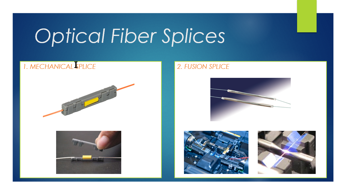
A splice permanently joins two fibers. There are two types of splices:
- Mechanical splice
- Fusion splice
It is extremely important in the splicing procedure to precisely align the two fiber ends when splicing. Good cleaving of fiber ends and cleanliness are also important during the splicing procedure.
A mechanical splice is a small fiber connector some 6 cm long and 1 cm in diameter. The connector precisely aligns the two bare fibers and makes a secure and permanent mechanical connection. The splice is fastened with a snap-type cover or adhesive binding or both may be used.
Mechanical splices are available as temporary or permanent splices. The insertion loss of a mechanical splice is somewhat greater than that of a fusion splice and is on the order of 0.1~0.8 dB.
There are additional splice process factors for mechanical (butt-spliced) joints. These include fiber end separation, fiber end angle, and Fresnel reflection.
Because single mode fibers have small optical cores and hence small mode-field diameters, they are less tolerant of misalignment at a fiber joint. Consequently, mechanical splices capable of achieving acceptable performance within a single-mode fiber system loss budget are somewhat more expensive to purchase, are more time-consuming to install, and may require capital equipment outlays equivalent to fusion splicing.
Single-fiber fusion splicing is the most widely used permanent method of joining optical fibers. Obtaining a good fusion splice is much easier today due to continued improvements to fusion splice equipment, procedures, and practices, in addition to the evolutionary improvements in controlling optical fiber geometries. As a result, insertion loss typically range from 0.04 to 0.10 dB for both single-mode and multimode fibers.
Fusion splice quality – two parameters affect the quality of a fusion splice: splice insertion loss and tensile strength.
In the case of multimode fibers, there are fiber-related factors that include core diameter mismatch, numerical aperture (NA) mismatch, index profile mismatch, and core/cladding concentricity error.
Concentricity refers to how well a fiber core is centered in the cladding circle – that is, that there is no offset from circularity. This loss can be reduced by using a splicing technique that aligns the fiber cores at the point of joining. From this figure, we can estimate the theoretical intrinsic splice loss for its major contributors: core diameter and NA mismatch. It should be noted that the splice loss is directional with regard to these variables (i.e., loss occurs only when optical propagation is across a joint in which the receiving fiber has the smaller core diameter of NA).
Splice loss values are additive, so if two multimode fibers that display mismatches in both core diameter and NA are joined, then their contribution to intrinsic loss is the sum of the two losses.
In the case of single-mode dispersion non-shifted fibers, the dominant fiber-related factor is Mode-Field Diameter (MFD) mismatch. This figure may be used to estimate the intrinsic loss contribution due to Mode-Field Diameter (MFD) mismatch.
As illustrated in this figure, the actual splice loss (bidirectional average) is practically nondirectional (i.e., the same fiber-related losses will be seen across the joint regardless of the direction of optical propagation). It should be taken into account that intrinsic loss is relatively low for Mode-Field Diameter mismatches expected within typical manufacturer’s tolerances. For instance, the loss would be approximately 0.04 dB for the worst-case fiber-related bidirectional loss for fiber having a 9.3 +/- 0.5 µm Mode-Field Diameter specification.
These are splice process-related factors as well. These factors are those induced by the splicing methods and procedures. Splice process factors involve lateral and angular misalignment, contamination, and core deformation. The effects can be minimized by using properly trained technicians, automated fiber-alignment equipment, and fusion cycles on the more modern equipment.
Preparation of the fiber optic cable for splicing involves the following tasks: fiber stripping, surface cleaning, and fiber end angle.
The fiber coating can be removed by a number of techniques such as chemical stripping, thermal stripping or mechanical stripping. For typical acrylate-coated fibers, mechanical stripping is good because it is safe, fast, and inexpensive and creates a well-defined coating termination.
Surface cleaning is very important. Any acrylate coating residue that remains after stripping should be removed from the bare fiber surface. Touching the bare fiber before fusion splicing should be avoided to prevent the fiber from being contaminated by dust or body oils.
The primary attribute affecting single-fusion splicing is end angle. Thus proper fiber end angle preparation is a fundamental step in obtaining an acceptable fusion splice. Requirements for fiber end angle vary from user to user and the type of cleaver used. In general, fiber end angles less than two degrees usually yield acceptable field fusion splices. However, one should expect end angles around half a degree when well-controlled cleavers are used.
There are manual and automatic fusion splice alignment units. The user first mounts the clean, cleaved fibers into alignment blocks and/or other holding mechanism of the splicer. The fibers are then visually aligned in the lateral (X-Y) directions. Visual alignment requires maintaining the smallest gap possible between the fibers to reduce the visual errors that may occur when manually aligning the edges of the fibers under magnification.
In the case of automatic alignment, the initial alignment involves nothing more than placing the fibers in the V-groove chucks. The alignment unit automatically aligns the fibers.
There are five equipment alternatives for final fiber core alignment:
- Power monitoring using a source and detector
- Use of Optical Time-Domain Reflectometer (OTDR) power monitoring
- Local injection and detection (LID) techniques
- Profile alignment techniques
- Passive V-groove alignment
The power monitoring technique bases optimum fiber alignment on the amount of optical power transferred through the splice joint. A light source is connected to the input end of one of the fibers to be fusion spliced. The light signal passes through the splice joint, and its level is read on a power meter at the output end. The alignment is achieved by moving the fibers in the X and Y lateral directions until a maximum power reading is achieved. Two people are required with this technique. One reads the power meter while the other, some distance away, operates the splicer. This method is an improvement over visual alignment in that it optimally aligns the fiber cores rather than the cladding.
An OTDR may be used instead of a remote power meter as in the method above. It should be noted that OTDR alignment depends on the ability of the OTDR to provide a real-time display of power for alignment optimization.
Many fusion splicers use a local injection and detection (LID) system. This is basically another power-alignment system that is self-contained at the fusion site. LIDs eliminate the need for remote monitoring of power level. With this device the fibers on either side of the splicing point are bent around cylindrical mandrels that are small enough to allow the injection of light through the fiber coating on the input side and detection on the output side.
Profile alignment systems present an image of the splice point to allow the technician to properly align the two fibers for a fusion splice. Collimated light is directed through the fibers at right angles to the fiber axis right at the splice point. This produces an image of the fiber that can be brought into alignment. One specialized type of profile alignment creates a computer-generated image of the core centerlines where the computer automatically brings the fibers into alignment prior to fusing.
Another profile alignment system carriers out the alignment procedure using the fiber-clad profile. It should be kept in mind that quality alignment depends a lot on the core-clad concentricity. With passive fixed V-groove alignment, the fiber alignment is a result of precision-machined V-grooves and precisely controlled fiber-clad diameter and core/clad concentricity.
The fusion process involves an electric arc for heating and fusing. Some technicians will apply one or more short bursts of arc current to remove any contaminants from the fiber points before starting the fusion procedures.
Pre-fusion is the next step. This is a heating process to soften the fiber ends to be joined. Pre-fusion is done to ensure that the fiber ends are at an optimum temperature during the final fusion step that allows the fibers to flow together upon physical contact. It the pre-fusion temperature is too high, there will be excessive fiber-end deformation that may result in a change in glass geometry. If the temperature is too low, mechanical deformation of the fiber ends may result. When this happens there will be fiber buckling as the fiber ends are forced together during the fusion step.
Optimum splicer settings include arc current and duration, gap distance, and overlap for the pre-fusion and fusion steps. The settings must be determined on a job-by-job basis.
Splice quality involves two principle parameters as discussed above. These are fiber strength and induced loss at the splice point. Some splicers have a pull test capability. Experienced technicians are known to use a manual pull test such that they can fairly estimate fiber strength.
Splice loss may be checked by remote OTDR or power meter using a method similar to the one described above for fiber alignment. Accurate measurement of splice loss by an OTDR requires averaged bidirectional measurement.