Among a group of optical receivers, a receiver is said to be more sensitive if it achieves the same performance with less optical power incident on it. The performance criterion for digital receivers is governed by the bit-error rate (BER), defined as the probability of incorrect identification of a bit by the decision circuit of the receiver. Hence, a BER of 2 x 10⁻⁶ corresponds to on average 2 errors per million bits. A commonly used criterion for digital optical receivers requires the BER to be below 1 x 10⁻⁹. The receiver sensitivity is then defined as the minimum average received power  required by the receiver to operate at a BER of 10-9. Since depends on the BER, let us begin by calculating the BER.
1. Bit-Error Rate

Figure (a) above shows schematically the fluctuating signal received by the decision circuit, which samples it at the decision instant tD determined through clock recovery. The sampled valued I fluctuates from bit to bit around an average value I1 or I0, depending on whether the bit corresponds to 1 or 0 in the bit stream. The decision circuit compares the sampled value with a threshold value ID and calls it bit 1 if I > ID or bit 0 if I < ID. An error occurs if I < ID for bit 1 because of receiver noise. An error also occurs if I > ID for bit 0. Both sources of errors can be included by defining the error probability as
BER = p(1)P(0|1) + p(0)P(1|0)
where p(1) and p(0) are the probabilities of receiving bit 1 and 0, respectively, P(0|1) is the probability of deciding 0 when 1 is received, and P(1|0) is the probability of deciding 1 when 0 is received. Since 1 and 0 bits are equally likely to occur, p(1) = p(0) = 1/2, and the BER becomes

Figure (b) above shows how P(0|1) and P(1|0) depend on the probability density function p(I) of the sampled value I. The functional form of p(I) depends on the statistics of noise sources responsible for current fluctuations. Thermal noise iT is well described by Gaussian statistics with zero mean and variance σT2. The statistics of shot-noise contribution is is also approximately Gaussian for p-i-n receivers although that is not the case for APDs. A common approximation treats is as a Gaussian random variable for both p-i-n and APD receivers but with different σs2 given by two equations, respectively. Since the sum of two Gaussian random variables is also a Gaussian random variable, the sampled value I has a Gaussian probability density function with variance σ2 = σs2 + σT2. However, both the average and the variance are different for 1 and 0 bits since Ip equals I1 or I0, depending on the bit received. If σ12 and σ02 are the corresponding variances, the conditional probabilities are given by

where erfc stands for the complementary error function, defined as

By substituting these two equations in the BER equation above, the BER is given by

This equation shows that the BER depends on the decision threshold ID. In practice, ID is optimized to minimize the BER. The minimum occurs when ID is chosen such that

The last term in this equation is negligible in most cases of practical interest, and ID is approximately obtained from

An explicit expression for ID is

when σ1 = σ0, ID = (I1 + I0)/2, which corresponds to setting the decision threshold in the middle. This is the situation for most p-i-n receivers whose noise is dominated by thermal noise (σT >> σs) and is independent of the average current. By contrast, shot noise is larger for bit 1 than for bit 0, since σs2 varies linearly with the average current. In the case of APD receivers, the BER can be minimized by setting the decision threshold in accordance with the equation above.
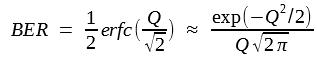
The BER with the optimum setting of the decision threshold is obtained by using the two equations above and depends only on the Q parameter as
 where the Q factor is obtained from the previous two equations and is given by

The approximate form of BER is obtained by using the asymptotic expansion of  and is reasonably accurate for Q > 3. The figure below shows how the BER varies with the Q parameter. The BER improves as Q increases and becomes lower than 10-12 for Q > 7. The receiver sensitivity corresponds to the average optical power for which Q ≈ 6, since BER ≈ 10-9 when Q = 6. Next subsection provides an explicit expression for the receiver sensitivity.
2. Minimum Received Power
The BER equation above can be used to calculate the minimum optical power that a receiver needs to operate reliably with a BER below a specified value. For this purpose the Q parameter should be related to the incident optical power. For simplicity, consider the case in which 0 bits carry no optical power so that P0 = 0, and hence I0 = 0. The power P1 in 1 bits is related to I1 as

where ![]() is the average received power defined as
is the average received power defined as  . The APD gain M is included in this equation for generality. The case of p-i-n receivers can be considered by setting M = 1.
The RMA (root mean square) noise currents σ1 and σ0 include the contributions of both shot noise and thermal noise and can be written as
σ1 = (σs2 + σT2)1/2 and σ0 = σT
Neglecting the contribution of dark current, the noise variances become

The Q factor is given by

For a specified value of BER, Q is determined from the BER equation above and the receiver sensitivity ![]() is found this Q equation. A simple analytic expression for
is found this Q equation. A simple analytic expression for ![]() is obtained by solving this Q equation for a given value of Q and is given by
is obtained by solving this Q equation for a given value of Q and is given by

This equation shows how ![]() depends on various receiver parameters and how it can be optimized. Consider first the case of a p-i-n receiver by setting M = 1. Since thermal noise σT generally dominates for such a receiver,
depends on various receiver parameters and how it can be optimized. Consider first the case of a p-i-n receiver by setting M = 1. Since thermal noise σT generally dominates for such a receiver, ![]() is given by the simple expression
is given by the simple expression

From the σT2 equation above, σT2 depends not only on receiver parameters such as RL and Fn but also on the bit rate through the receiver bandwidth Δf (typically, Δf = B/2). Thus, ![]() increases as
increases as ![]() in the thermal-noise limit. As an example, consider a 1.55-μm p-i-n receiver with R = 1 A/W. If we use σT = 100 nA as a typically value and Q = 6 corresponding to a BER of 10-9, the receiver sensitivity is given by
in the thermal-noise limit. As an example, consider a 1.55-μm p-i-n receiver with R = 1 A/W. If we use σT = 100 nA as a typically value and Q = 6 corresponding to a BER of 10-9, the receiver sensitivity is given by  or -32.2 dBm.
The ![]() equation above shows how receiver sensitivity improves with the use of APD receivers. If thermal noise remains dominant,
equation above shows how receiver sensitivity improves with the use of APD receivers. If thermal noise remains dominant, ![]() is reduced by a factor M, and the received sensitivity is improved by the same factor. However, shot noise increases considerably for APD, and the
is reduced by a factor M, and the received sensitivity is improved by the same factor. However, shot noise increases considerably for APD, and the ![]() equation above should be used in the general case in which shot-noise and thermal-noise contributions are comparable. Similar to the case of SNR discussed in the last tutorial, the receive sensitivity can be optimized by adjusting the APD gain M. It is easy to verify that
equation above should be used in the general case in which shot-noise and thermal-noise contributions are comparable. Similar to the case of SNR discussed in the last tutorial, the receive sensitivity can be optimized by adjusting the APD gain M. It is easy to verify that ![]() is minimum for an optimum value of M given by
is minimum for an optimum value of M given by

And the minimum value is given by

The improvement in receiver sensitivity obtained by the use of an APD can be estimated by comparing the following two equations for p-i-n and APD receivers, respectively:

It depends on the ionization-coefficient ratio kA and is larger for APDs with a smaller value of kA. For InGaAs APD receivers, the sensitivity is typically improved by 6-8 dB; such an improvement is sometimes called the APD advantage. Note that ![]() for APD receivers increases linearly with the bit rate B (Δf ≈ B/2), in contrast with its
for APD receivers increases linearly with the bit rate B (Δf ≈ B/2), in contrast with its ![]() dependence for p-i-n receivers. The linear dependence of
dependence for p-i-n receivers. The linear dependence of ![]() on B is a general feature of shot-noise-limited receivers. For an ideal receiver for which σT = 0, the receiver sensitivity is obtained by setting M = 1 in the
on B is a general feature of shot-noise-limited receivers. For an ideal receiver for which σT = 0, the receiver sensitivity is obtained by setting M = 1 in the ![]() equation above and is given by
equation above and is given by

A comparison of this equation and the  equation above shows sensitivity degradation caused by the excess-noise factor in APD receivers.
Alternative measures of receiver sensitivity are sometimes used. For example, the BER can be related to the SNR and to the average number of photons NP contained within the "1" bit. In the thermal-noise limit σ0 ≈ σ1. By using I0 = 0, we get Q = I1/2σ1. As SNR = I12/σ12, it is related to Q by the simple relation SNR = 4Q2. Since Q = 6 for a BER of 10-9, the SNR must be at least 144 or 21.6 dB for achieving BER <= 10-9. The required value of SNR changes in the shot-noise limit. In the absence of thermal noise, σ0 ≈ 0, since shot noise is negligible for a "0" bit if the dark-current contribution is neglected. Since Q = I1/σ1 = (SNR)1/2 in the shot-noise limit, an SNR of 36 or 15.6 dB is enough to obtain BER = 1 x 10⁻⁹. It was shown that SNR ≈ ηNP in the shot-noise limit. By using Q = (ηNP)1/2, the BER is given by

For a receiver with 100% quantum efficiency (η = 1), BER = 1 x 10⁻⁹ when NP = 36. In practice, most optical receivers require NP ~ 1000 to achieve a BER of 10-9, as their performance is severely limited by thermal noise.
3. Quantum Limit of Photodetection
The BER expression above obtained in the shot-noise limit is not totally accurate, since its derivation is based on the Gaussian approximation for the receiver noise statistics. For an ideal detector (no thermal noise, no dark current, and 100% quantum efficiency), σ0 = 0, as shot noise vanishes in the absence of incident power, and thus the decision threshold can be set quite close to the 0-level signal. Indeed, for such an ideal receiver, 1 bits can be identified without error as long as even one photon is detected. An error is made only if a 1 bit fails to produce even a single electron-hole pair. For such a small number of photons and electrons, shot-noise statistics cannot be approximated by a Gaussian distribution, and the exact Poisson statistics should be used. If NP is the average number of photons in each 1 bit, the probability of generating m electron-hole pairs is given by the Poisson distribution
 The BER can be calculated by using the two following equations:


The probability P(1|0) that a 1 bit is identified when 0 is received is zero since no electron-hole pair is generated when NP = 0. The probability P(0|1) is obtained by setting m = 0 in the equation above, since a 0 is decided in that case even though 1 is received. Since P(0|1) = exp(- NP), the BER is given by the simple expression
BER = exp(- NP)/2
For BER < 10-9 , NP must exceed 20. Since this requirement is a direct result of quantum fluctuations associated with the incoming light, it is refereed to as the quantum limit. Each 1 bit must contain at least 20 photons to be detected with a BER < 10-9 . This requirement can be converted into power by using P1 = NPhνB, where B is the bit rate and hν the photon energy. The receiver sensitivity, defined as  , is given by

The quantity ![]() expresses the receiver sensitivity in terms of the average number of photons/bit and is related to NP as
expresses the receiver sensitivity in terms of the average number of photons/bit and is related to NP as  when 0 bits carry no energy. Its use as a measure of receiver sensitivity is quite common. In the quantum limit
 ![]() = 10. The power can be calculated. For example, for a 1.55-μm receiver (hν = 0.8 eV),
= 10. The power can be calculated. For example, for a 1.55-μm receiver (hν = 0.8 eV), ![]() = 13 nW or -48.9 dBm at B = 10 Gb/s. Most receivers operate away from quantum limit by 20 dB or more. This is equivalent to saying that
= 13 nW or -48.9 dBm at B = 10 Gb/s. Most receivers operate away from quantum limit by 20 dB or more. This is equivalent to saying that ![]() typically exceeds 1000 photons in practical receivers.
typically exceeds 1000 photons in practical receivers.