This is a continuation from the previous tutorial - Gaussian Beam.
The characteristics of reflection and refraction of an optical wave at the interface of two different media depend on the properties of the media. We first consider the simple case of reflection and refraction at the planar interface of two dielectric media that are linear, lossless, and isotropic. In this situation, the permittivities ε1 and ε2 of the two media are constant real scalars, while the permeabilities are simply equal to μ0 at optical frequencies. We assume that the optical wave is incident from medium 1 with a wavevector ki, while the reflected wave has a wavevector kr, and the transmitted wave has a wavevector kt.
Because an optical wave varies with exp(ik⋅r - iωt), the condition that
\[\tag{143}\mathbf{k}_\text{i}\cdot\mathbf{r}=\mathbf{k}_\text{r}\cdot\mathbf{r}=\mathbf{k}_\text{t}\cdot\mathbf{r}\]
is required at the interface for the boundary conditions described by (17) - (20) [refer to the optical fields and Maxwell's equations tutorial] to be satisfied at all points along the interface at all times. This implies that the three vectors ki, kr, and kt lie in the same plane known as the plane of incidence, as shown in figure 16 and 17 below.

The projections of these three wavevectors on the interface are all equal so that
\[\tag{144}k_i\sin{\theta_i}=k_r\sin{\theta_r}=k_t\sin{\theta_t}\]
where θi is the angle of incidence, and θr and θt are the angle of reflection and the angle of refraction, respectively, for the reflected and transmitted waves. All three angles are measured with respect to the normal \(\hat{n}\) of the interface, as is shown in figure 16 and 17.
Because ki = kr and ki/kt = n1/n2, (144) yields the relation
\[\tag{145}\theta_i=\theta_r\]
and the following familiar Snell law for refraction:
\[\tag{146}n_1\sin{\theta_i}=n_2\sin{\theta_t}\]
By expressing H in terms of k x E in the form of (86) [refer to the propagation in an isotropic medium tutorial] with appropriate values of k for the incident, reflected, and refracted fields, the amplitudes of the reflected and transmitted fields can be obtained from the boundary conditions in (17) and (18) [refer to the optical fields and Maxwell's equations tutorial]. There are two different modes of field polarization.
TE Polarization (s wave, σ wave)
The electric field is linearly polarized in a direction perpendicular to the plane of incidence while the magnetic field is polarized parallel to the plane of incidence, as shown in figure 16. This is called transverse electric (TE) polarization or perpendicular polarization. This wave is also called s polarized, or σ polarized. In this case, the reflection coefficient, r, and the transmission coefficient, t, of the electric field are given by the following Fresnel equations:
\[\tag{147}r_s\equiv\frac{\mathcal{E}_r}{\mathcal{E}_i}\equiv\frac{n_1\cos\theta_i-n_2\cos\theta_t}{n_1\cos\theta_i+n_2\cos\theta_t}=\frac{n_1\cos\theta_i-\sqrt{n_2^2-n_1^2\sin^2\theta_i}}{n_1\cos\theta_i+\sqrt{n_2^2-n_1^2\sin^2\theta_i}}\]
\[\tag{148}t_s\equiv\frac{\mathcal{E}_t}{\mathcal{E}_i}=\frac{2n_1\cos\theta_i}{n_1\cos\theta_i+n_2\cos\theta_t}=\frac{2n_1\cos\theta_i}{n_1\cos\theta_i+\sqrt{n_2^2-n_1^2\sin^2\theta_i}}\]
respectively. The intensity reflectance and transmittance, R and T, which are also known as reflectivity and transmissivity, respectively, are given by
\[\tag{149}R_s\equiv\frac{I_r}{I_i}=\frac{|\bar{\mathbf{S}}_r\cdot\hat{n}|}{|\bar{\mathbf{S}}_i\cdot\hat{n}|}=\left|\frac{n_1\cos\theta_i-n_2\cos\theta_t}{n_1\cos\theta_i+n_2\cos\theta_t}\right|^2\]
\[\tag{150}T_s\equiv\frac{I_t}{I_i}=\frac{|\bar{\mathbf{S}}_t\cdot\hat{n}|}{|\bar{\mathbf{S}}_i\cdot\hat{n}|}=1-R_s\]
TM Polarization (p wave, π wave)
The electric field is linearly polarized in a direction parallel to the plane of incidence while the magnetic field is polarized perpendicular to the plane of incidence, as shown in figure 17 below.

This is called transverse magnetic (TM) polarization or parallel polarization. This wave is also called p polarized, or π polarized. In this case, the reflection and transmission coefficients of the electric field are given by the following Fresnel equations:
\[\tag{151}r_p\equiv\frac{\mathcal{E}_r}{\mathcal{E}_i}=\frac{n_2\cos\theta_i-n_1\cos\theta_t}{n_2\cos\theta_i+n_1\cos\theta_t}=\frac{n_2^2\cos\theta_i-n_1\sqrt{n_2^2-n_1^2\sin^2\theta_i}}{n_2^2\cos\theta_i+n_1\sqrt{n_2^2-n_1^2\sin^2\theta_i}}\]
\[\tag{152}t_p\equiv\frac{\mathcal{E}_t}{\mathcal{E}_i}=\frac{2n_1\cos\theta_i}{n_2\cos\theta_i+n_1\cos\theta_t}=\frac{2n_1n_2\cos\theta_i}{n_2^2\cos\theta_i+n_1\sqrt{n_2^2-n_1^2\sin^2\theta_i}}\]
respectively. The intensity reflectance and transmittance for TM polarization are given, respectively, by
\[\tag{153}R_p\equiv\frac{I_r}{I_i}=\left|\frac{n_2\cos\theta_i-n_1\cos\theta_t}{n_2\cos\theta_i+n_1\cos\theta_t}\right|^2\]
\[\tag{154}T_p\equiv\frac{I_t}{I_i}=1-R_p\]
Several important characteristics of the reflection and refraction of an optical wave at an interface between two media are summarized.
1. For both TE and TM polarization, R = |r|2 and R + T = 1, but T ≠ |t|2.
2. If n1 < n2, light is incident from a rare medium upon a dense medium. In this case, the reflection is called external reflection. If n1 > n2, light is incident from a dense medium on a rare medium, and the reflection is called internal reflection.
3. Normal incidence. In the case of normal incidence, θi = θt = 0. There is no difference between TE and TM polarizations, and
\[\tag{155}R=\left|\frac{n_1-n_2}{n_1+n_2}\right|^2,\qquad T=1-R=\frac{4n_1n_2}{(n_1+n_2)^2}\]
For the case of external reflection at normal incidence, there is a 180° phase reversal for the reflected electric field with respect to the incident field. For internal reflection, the phase of the reflected field is not reversed at normal incidence. However, the values of R and T do not depend on which side of the interface the wave comes from.
4. Brewster angle. For a TE wave, Rs increases monotonically with the angle of incidence. For a TM wave, Rp first decreases then increases as the angle of incidence increases. For the interface between two lossless media, Rp = 0 at an angle of incidence θi = θB, where
\[\tag{156}\theta_B=\tan^{-1}\frac{n_2}{n_1}\]
is known as the Brewster angle. When θi = θB, the angle of refraction for the transmitted wave is
\[\tag{157}\theta_t=\frac{\pi}{2}-\theta_B\]
It can be shown that this angle is the Brewster angle for the same wave incident from the other side of the interface. Figure 18(a) shows the reflectance of TE and TM waves as a function of the angle of incidence for external reflection at the interface between two media of refractive indices of 1 and 3.5.
These characteristics are very useful in practical device applications:
(a) At θi = θB, a TM-polarized wave is totally transmitted, resulting in a perfect lossless window for TM polarization - such windows are called Brewster windows and are useful as laser windows.
(b) At θi = θB, the reflected wave is completely TE polarized - linearly polarized light can be produced by a reflection-type polarizer based on this principle.
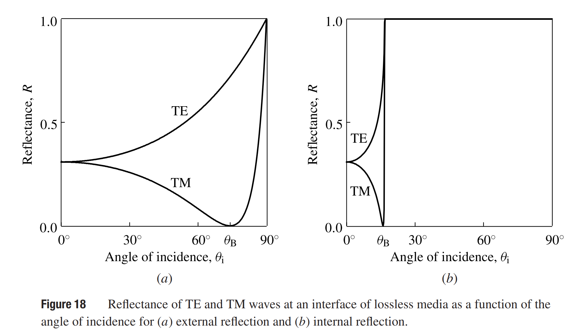
5. Critical angle. In the case of internal reflection with n1 > n2, total internal reflection occurs if the angle of incidence θi is larger than the angle
\[\tag{158}\theta_c=\sin^{-1}\frac{n_2}{n_1}\]
which is called the critical angle. The reflectance of TE and TM waves as a function of angle of incidence for internal reflection at the interface between two media of refractive indices of 1 and 3.5 is shown in figure 18(b). Note that the Brewster angle for internal reflection is always smaller than the critical angle.
6. If one or both media have a loss or gain, the indices of refraction become complex. In this situation, the reflectance of the TM wave has a minimum that does not reach zero, as shown in figure 19 for external reflection.

7. For wave propagation in a general direction in an anisotropic medium, there are two normal modes that have different indices of refraction. The refracted fields of these two normal modes can propagate in different directions, resulting in the phenomenon of double refraction. Meanwhile, the Poynting vector does not have to be in the plane of incidence.
8. Optical media are generally dispersive. Therefore, reflectance and transmittance, as well as the direction of the refracted wave, are generally frequency dependent.
Example
Water has an index of refraction n = 1.33. The index of refraction of ordinary glass is approximately n = 1.5. For most semiconductors, such as Si, GaAs, and InP, the index of refraction is often in the range between 3 and 4, depending on the optical wavelength and the material. Her we take a nominal value of n = 3.5 for a semiconductor. Find the reflectivities at normal incidence, the Brewster angles, and the critical angles for these media at their interfaces with air.
Using the formula given in (155) for the reflectivity at normal incidence, we find that R = 0.02 for water, R = 0.04 for ordinary glass, and R typically falls in the range of 0.3 and 0.32 for a semiconductor.
Using (156) for the Brewster angle, we find that θB ≈ 54° for water, θB ≈ 56° for ordinary glass, and θB is typically around 74° for a semiconductor.
Using (158) for the critical angle, we find that θc ≈ 49° for water, θc ≈ 42° for ordinary glass, and θc is around 17° for a semiconductor.
The next part continues with the Phase Velocity, Group Velocity, and Dispersion tutorial.