Jones Matrix
For background information about Jones vectors, please check out this article.
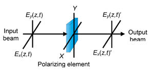
We now study the matrix forms for polarizing elements. In order to do this, we have an assumption:
The components of a light beam emerging from a polarizing element are linearly related to the components of the incident light beam.

This relationship can be expressed in equations as:

where Ex', Ey' are the components of the emerging light beam, and Ex , Ey are the components of the incident light beam.
The quantities Jxx, Jxy, Jyx, Jyy are the transforming factors of this polarizing element.
We can rewrite (1) in a matrix form:

or

where

Here J is a 2x2 matrix, and is called the Jones matrix for the polarizing element.
Jones Matrix for a Polarizer
A linear polarizer doesn't affect the vibration direction of either Ex (vibration along x axis) or Ey (vibration along y axis).
What this means is that Ey contributes nothing to Ex' since their vibration directions are perpendicular to each other, and a linear polarizer doesn't affect their vibration directions in any way (unlike a wave plate).
This also means that Ex contributes nothing to Ey' for the same reason.
So based on this fact, we can get the following relations:


We can then write (5) in Jones matrix form as:

So the Jones matrix for a polarizer is

1. Linear Horizontal Polarizer
For a linear horizontal polarizer, Ex passes through completely, and Ey is blocked completely. so (7) becomes:

2. Linear Vertical Polarizer
For a linear vertical polarizer, Ex is blocked completely, and Ey passes through completely. so (7) becomes:

3. Linear Polarizer Rotated Through an Angle θ
It is more useful to know the Jones matrix for a linear polarizer rotated through an angle θ.
In this sense, linear horizontal polarizer (θ = 0 or π) and vertical polarizer (θ = π/2 or 3π/2) are just two special cases.
We can use rotation transformation to achieve the new J' as:

where J(θ) is the rotation matrix:

For more information about rotation matrix, please read this article.
So for a rotated linear polarizer represented by (7) and rotated by angle θ we can get:

By doing the matrix multiplication, we find that the Jones matrix for a rotated linear polarizer is:

For an ideal linear polarizer we can set px = 1 and py = 0 in (13), so that Jones matrix for a rotated linear horizontal polarizer is:

We can see that for θ = 0° (horizontal) and θ = 90° (vertical), (14) gives the Jones matrices for a linear horizontal polarizer and vertical polarizer as shown by (8) and (9) respectively.
Based on (14), the Jones matrix for a linear polarizer rotated +45° can be calculated as:

4. Non-ideal Linear Polarizer
If the linear polarizer is not ideal, then the Jones matrix for a polarizer (7) at θ = +45° is concluded from (13) to be:

Jones Matrix for a Retarder (Phase Shifter, Waveplate)
A waveplate or retarder is an optical device that alters the polarization state of a light wave travelling through it.
Two common types of waveplates are
- Half-wave plate, which shifts the polarization direction of linearly polarized light.
- Quarter-wave plate, which converts linearly polarized light into circularly polarized light and vice versa. A quarter wave plate can be used to produce elliptical polarization as well.

Waveplates are constructed out of a birefringent material (such as quartz or mica), for which the index of refraction is different for different orientations of light passing through it.
The behavior of a waveplate (that is, whether it is a half-wave plate, a quarter-wave plate, etc.) depends on the thickness of the crystal, the wavelength of light, and the variation of the index of refraction.
By appropriate choice of the relationship between these parameters, it is possible to introduce a controlled phase shift between the two polarization components of a light wave, thereby altering its polarization.
The retarder (waveplate) increases the phase by +φ/2 along the fast (x) axis and retards the phase by -φ/2 along the slow (y) axis.
The relationship between the incident light beam components Ex, Ey and the emerging light beam components Ex', Ey' is:

We can write (17) in Jones formalism as:

From (18), we can get the Jones matrix for a retarder (phase shifter) as:

where φ is the total phase shift between Ex' and Ey'.
1. Jones matrix for quarter-waveplate
For a quarter-waveplate, the phase different φ = 90°. So we get:

2. Jones matrix for half-waveplate
For a half-waveplate, the phase difference φ = 180°. So we get:

In (21), we used Euler's formula as shown below. Learn more about Euler's formula for complex analysis here.

3. Jones matrix for a rotated waveplate (retarder)
Just as the case for linear polarizer rotated through an angle θ as shown in (10), we can also conclude the Jones matrix for a rotated waveplate by angle θ.
The conclusion process involves using (19), (10), and (11) and the resultant Jones matrix is:

With the half-angle formulas, (22) can be written as:

From (23), we get the Jones matrix for a quarter-waveplate as:

Similarly, we get the Jones matrix for a half-waveplate as:

The factor i in (25) is unimodular and can be suppressed. It is common, therefore, to write (25) simply as:

Jones Matrix for a Rotator (i.e. Faraday Rotator)
A polarization rotator rotates the polarization state (polarization ellipse) of an incident beam by an angle θ as shown below.
We define angle θ to be positive for counterclockwise rotation, and negative for clockwise rotation.

So from amplitudes projection, we see that:
- Ex contributes (cosθ•Ex) to E'x, Ey contributes (sinθ•Ey) to E'x
- Ex contributes (-sinθ•Ex) to E'y, Ey contributes (cosθ•Ey) to E'y
Thus we write them into an equation:

We put them into the matrix form as:

So the Jones matrix for a polarization rotator is:

Jones matrix for a rotated (angle φ) rotator
Here is a very interesting fact:
The incident beam's polarization ellipse (state) can only be rotated by an amount θ intrinsic to a rotator. The mechanical rotation of a rotator does not affect the rotation angle θ at all!
In other words, no matter how you rotate a rotator by any angle φ, the emerging beam's polarization ellipse is only rotated by an angle θ in respective to the incident beam's polarization ellipse.
Proof:
In reference to (10), (11) and (29), the Jones matrix for a rotated rotator (by an angle φ) is:

we then get:

After carrying out the matrix multiplication in (30), we then get:

Isn't that amazing?
Jones Matrix Calculus Application Examples
An application of the Jones matrix calculus is to determine the intensity of an output beam when a rotating polarizer is placed between two crossed polarizers as shown below.

So first we need to find the Jones matrix for the whole system. The output beam E' is
E' = J • E
In reference to (8), (9), and (14), we then get the Jones matrix for the whole system J as:

Since the first LHP is a linear polarizer on x axis, as seen equation (16) from this article (click to open in another window), the normalized Jones vector for linear horizontally polarized light is

Thus since E' = J • E, we then get

From (9), (10), (11), and (12) from the same reference article, we find the complex transpose E† of output beam E' as

And intensity I' of the output beam is
I' = E† • E
We then get I'

By repeatedly using the following trigonometry formulas:

We can then get:

We can plot I' in respective to θ in a graph.
