Table of Contents
Fiber optic tool kit and SC connectors
Fiber Optic Tool Kit:
The fiber optic tool kit contains tools to assemble SC connectors. Required consumables are sold separately.

Consumables Kit:
The consumables kits for single mode and multimode connectors are show below. Each contains polishing paper (lapping films) and other materials required to assemble the connectors.
Diamond lapping films (polishing papers) are used to remove zirconia ferrule material, this is needed when a glass fiber breaks off below the ferrule surface.

Adhesives:
Adhesives need to be purchased separately. Adhesives have a shelf life. They are sold separately to allow better material management by separating the adhesives from polishing materials that do not have a shelf life.

SC Connectors:
SC connectors components are listed below.

Step 1: Cable and fiber preparation
1. Place cable support (rubber boot) and crimp sleeve onto fiber cable
Slip the cable support (rubber boot) and the crimp sleeve onto the fiber cable.

2. Measure and mark cable
Using either a scale or template, measure and mark the cable 34mm (1.35 inch) from the end of cable
3. Remove outer jacket
Using the outer jacket removal notch on the 5-in-1 fiber stripping tool, remove the outer jacket back to the mark.


4. Insert sheath tube into cable jacket
For 3mm cable, insert the sheath tube over the buffer fiber and into the cable jacket

5. Trim strength member (Kevlar)
With the Kevlar (fiber strength member yarn) separated into two equal size bundles, use the Kevlar cutter to trim the strands 6mm (0.25 inch) from the edge of the outer jacket. Flair the Kevlar yarn evenly all around the cable.

6. Measure and mark buffered fiber
Measure and mark the buffered fiber 19mm (0.75 inch) from the end of the buffered fiber
7. Remove buffer and fiber coating
Refer to the Micro-Strip heat-strip tool instructions for setup.

Make sure heater unit is fully inserted. Insert buffered fiber through the guide tube to allow 19mm (0.75 inch) of the buffer and coating to be removed.
Close the handles and wait 6 to 10 seconds for the buffer coating to be softened.
Pull the fiber from the tool with one smooth motion.

Wipe the stripped fiber with a wipe dampened with isopropyl alcohol to remove any residual coating.
Recommended dimensions:
The recommended dimensions for the prepared cable and fiber are shown below.

8. Set aside prepared cable
Place the prepared cable onto the fiber holder block in the tool kit.
Step 2: Epoxy Preparation
1. Remove epoxy divider
This is a two-part epoxy separated with a divider. The divider must be removed to allow the epoxy to be mixed.
2. Mix the epoxy
Using the divider, thoroughly mix the epoxy until both parts are blended into a smooth, uniform color

3. Install the syringe tip
Place the syringe tip onto the syringe and twist to lock it in place. Then remove the plunger to allow the mixed epoxy to be loaded into the syringe.

4. Pour mixed epoxy into syringe
Fold the epoxy package in half, cut the corner of the package, and squeeze the mixed epoxy into the syringe.

Replace the plunger in the syringe.
5. Remove air from syringe
Remove air pockets fro the syringe by holding the syringe tip upward and ejecting epoxy until the air pockets are removed.
Step 3: Connector Installation
1. Inject epoxy into connector body
Gently insert the syringe tip through the tubing in the back of the connector body until it bottoms against the ferrule.
Inject the epoxy into the ferrule until a bead of epoxy forms on the tip of the ferrule.

The epoxy bead should cover at least one-half of the ferrule end face.
Withdraw the syringe tip from the connector body, but maintain slight pressure on the syringe to coat the inside diameter of the metal ferrule flange (barrel) with the epoxy.
Important: DO NOT fill the plastic tubing with epoxy. DO NOT allow the epoxy to get onto the connector housing components.
2. Insert fiber into connector body
Immediately insert the fiber through the connector body, carefully feeling for the ferrule capillary.
Rotate the connector body as the fiber is inserted to allow the fiber to pass through the connector body without hanging up.

Be careful not to break the fiber.
3. Install cable sleeve
Slip the cable sleeve (crimp sleeve) over the outer jacket and the connector body to capture the Kevlar yarn between the connector body and sleeve.

4. Secure crimp sleeve
Before crimping, make sure the sleeve is fully seated on the cable retention member.
Align the crimp sleeve with the SC cavity of the crimping tool and squeeze the tool handles until they release.


5. Install cable support (rubber boot)
Push the cable support (rubber boot) over the crimp sleeve and onto the connector body.

6. Install connector holder
Place the connector body in a connector holder.

Step 4: Cure the Epoxy
1. Set-up the curing oven
Place the oven away from combustibles, and plug into a power outlet.
Turn on the curing oven, the switch will illuminate, indicating that the power is on.
In about 5 minutes, an illuminated READY lamp indicates that the oven is ready for use.
Important: If terminating 1.6mm jacket fiber cable, place the Heat Tube Assembly Fixtures into the ports of the oven.

2. Place connector into oven
Place the connector and holder assembly into one of the oven ports.

Cure for 10 minutes.
3. Cool down the connector assembly
After 10 minutes of curing time, remove the connector and holder assembly and place it into one of the ports in the holder block to cool.

Step 5: Cleave Fiber and Polish Connector Ends
1. Cleave the fiber
Remove the connector holder from the connector body.
Using one stroke with the cleaving tool, score the fiber close to the crest of the epoxy bead.

2. Pull away the fiber stub
Using a gentle straight pull, remove the exposed fiber.
If the fiber does not pull off with a gentle pull, re-score on the opposite side of the fiber.
3. Prepare polishing material
Before positioning the polishing material, clean the bare polishing plate and the back of the non-foam-backed polishing paper (lapping film) with a wipe dampened with isopropyl alcohol.
Blow the polishing plate and film dry with canned air.
Important: Foreign material can cause scratches on the end face of the ferrule if the polishing plate or paper is not properly cleaned.
4. Prepare polishing tool
Clean the surface of the polishing tool (polishing puck) and the connector tip with a wipe dampened with alcohol.
5. Air polish the cleaved fiber
Hold the 12um (or 15um) polishing paper (lapping film), dull side against the connector.
Point the connector ferrule upward and, using light circular or figure-8 strokes, polish the cleaved fiber down flush with the epoxy bead.

Note: This will reduce the risk of breaking the fiber during the first polishing.
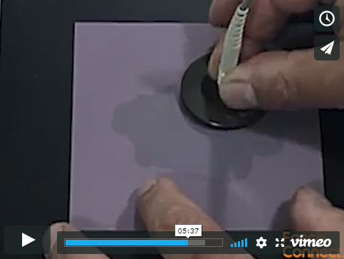
6. Insert connector into polishing tool (polishing puck)
Insert the connector tip into the polishing tool (puck).

7. First polish - single mode and multimode connectors
Place a sheet of 3um polishing paper over the plate.
Carefully place the connector ferrule into the polishing tool (puck).
Starting with extremely light pressure, polish the connector using figure-8 strokes until all epoxy has been removed.

Check periodically with the eye loupe or magnifier to verify that all of the epoxy has been removed.

No Further polishing is required for multimode connectors.
Note: Extremely light pressure should be used during the first few polishing strokes to avoid breaking the fiber.
Start with a fresh area of the polishing paper (lapping film) for each connector to be polished.
Remove the connector from the polishing tool and clean both the connector and the tool with a wipe dampened with isopropyl alcohol.
Then use canned air to dry the connector and the tool.
8. Second polish - single mode connectors
To achieve optimum return loss, place the 1um polishing paper (lapping film) onto a polishing pad.

Add a small amount of distilled water to the portion of the film that will be the working area. Using the polishing tool (puck), work the water into the polishing paper.
Place the connector ferrule into the polishing tool and polish the connector ferrule for 6 to 8 strokes; each stroke should be approximately 51mm (2 inches) in height.

Warning: DO NOT exceed 15 strokes.
Step 6: Inspection
1. Attach connector to microscope
Insert the connector tip into the bottom of the microscope. Open the microscope barrels to illuminate the connector tip, and use the side wheel to focus.
A high-intensity light may be used at the other end of the fiber to illuminate the core area.

The core may not necessarily illuminate if an epoxy film or bead still exists on the connector end face.
2. Inspect fiber end
An acceptable fiber end is free of cracks. Voids or scratches must be avoided in the core area.

If the fiber is unacceptable, then the fiber must be re-terminated.
3. Put on the dust cap
If the connector is not to be used right away, cover the connector end with a protective dust cap.
Repairs (Domed Connectors Only)
When the fiber is cracked or scratched in or near the core, the ferrule in some instances can be repaired (but a re-termination is preferred).